RC Spread Spectrum Demystified
by
David E. Buxton April 27, 2014
Go to a regional fun fly or national event to watch all the airplanes and helicopters flying without need of a frequency board.
You have to wonder how it works. Is it true that the full 80 MHz wide 2.4 GHz band can support as many as 200 airplanes? If you are like me, you are not willing to accept that several radios can share the same frequency until you understand how it’s done.

This article has evolved considerably, woven with popular theories and explanations that each in their turn were found to be incorrect. All too often the correct information is buried in theoretical formulas that few of you would care to understand. The objective of this article is to present the theory of how our RC radios work in a format that each of you can understand.
2.4 GHz RC Spread Spectrum
The following are three important technologies used by our 2.4 GHz band radios. A frequency band that is increasingly popular for a growing variety of commercial products as well:
- FHSS (Frequency Hopping Spread Spectrum): Transmitter and receiver hop in unison to a mutually common pseudo random sequence of frequencies. One or more packets of data are transmitted before each hop.
- DSSS (Direct Sequence Spread Spectrum): Digital sequence modulation applied to the carrier frequency. Looks like noise on a spectrum analyzer. The recommended form of modulation used by FHSS for transmitting data.
- CRC (Cyclical Redundancy Code): A key premise is that data sometimes gets corrupted. The transmitter’s and receiver’s CRC calculation won’t match if even one bit is off. RC receivers ignore flawed packet’s, Wi-Fi asks for a retry.
Futaba’s first 2.4 GHz RC radios started out with 10 kHz modulated FHSS and later models added DSSS which was introduced as FASST. Spektrum’s DSSS only system (no hopping) was introduced as DSM which was later enhanced with two hopping frequencies called DSM2, more recently followed with 23 hopping FHSS frequencies called DSMX.

Figure 1 to the left illustrates how DSSS modulation is used for each of 36 FHSS frequencies.
The following table illustrates with a few examples that DSSS and FHSS are both being used. All of the currently marketed 2.4GHz RC radios that I know of are now using both.

Code Division Multiple Access (CDMA)
CDMA is the DSSS technology used by our RC radios. For us, Multiple Access means it is designed for several radios on the same frequency.

Figure 2 here to the right illustrates how each data bit is expanded using several encoding bits. Note that the encoding pattern for a ‘0’ data bit and a ‘1’ data bit are a flipped image of each other.
The higher the ratio of coding bits for each data bit the better the DSSS process can extract data from noise. The ratio is referred to as Process Gain (which will be illustrated and explained later). RC radios use a much higher process gain than Wi-Fi. Both DSSS encoded signals can travel as far, but our radios can extract clean data packets at a much greater distance than Wi-Fi. Here are three process gain examples that help to explain a key benefit of DSSS:
- Most (perhaps all) Wi-Fi uses a process gain of 11. Range is about 850 ft outdoors.
- Spektrum and other radios use 64 bit CDMA codes. Range is 2 to 3 miles or more, a mile or less for Park Fliers.
- GPS (not 2.4 GHz) has a process gain of 1024. Satellite altitude is about 12,550 miles (20,200 km). GPS satellites use a common frequency for the 24 to 32 US satellites which use different DSSS codes without any frequency hopping.
Communicating Edges
It is important to understand that CDMA communicates at the edges of each coding bit and not the high or low levels.
This section will help you understand how it works.
Those of you with an electronics background understand the relationship between rise time and bandwidth.
The faster a signal shifts from one level to another, the wider the spread of harmonics and the wider the bandwidth.
The same thing happens if a signal shifts between two frequencies or shifts between two phases (e.g. 180 degrees, 90 degrees) of the same frequency. The faster the shift the wider the band-width of the spread spectrum.
There are spread spectrum Shift Key (SK) technologies that accomplish CDMA edge modulation by shifting between two frequencies, two or four phases or amplitudes.

Figure 3 to the right illustrates Shift Keying. Each rapid shift results in a narrow pulse of spread spectrum energy that looks like noise with a frequency response spread as seen on a spectrum analyzer. Most of our RC radios use Gaussian Frequency Shift Keying (GFSK). “Gaussian” specifies the type of shaping filter used to translate the shift keying into spread spectrum. The Gaussian filter optimizes performance while reducing the bandwidth. In this case less band-width can be a good thing.
Receiver Decoding

The CDMA illustration to the left is applicable for the different forms of shift keying. A multiplier circuit is fed with a pattern of 0s, 1s and -1s timed by the DSSS code series used by the transmitter.
Most of the time the incoming signal is being ignored because it is being multiplied by 0. Two radio systems out of sync with each other will not see each other. A Phase Lock Loop (PLL) plays a vital roll in keeping your receiver’s 2.4 GHz clock in sync with your transmitter’s clock. The PLL acts like a flywheel to keep the receiver’s clock on track until the next edge is detected. The PLL speeds up or slows down to accommodate Doppler shift.
The following Figure 5 uses an illustratively short DSSS code.

The output of the multiplier circuit connects to an integrator that accumulates the sum of each edge. The longer the series of coding bits, the higher the staircase will rise or descend for a final determination at the end of each data bit series. A successful decode is accomplished as long as the final summation is correctly positive or negative. The following crude simulation uses a 64 bit DSSS code and noise that is more than 200 times stronger than the signal.

As mentioned already, the number of bits in the DSSS code pattern is referred to as process gain. Increasing the gain increases your receiver’s ability to lift your transmitter’s faint signals out of the noise at a considerable distance. It also helps to separate your radios signal from that of other radios that may have hopped to your radio’s cur-rent frequency.
CDMA timing and process gain make it possible for several radios to share the same frequency. Explains why 2.4 GHz microwave ovens and basic Wi-Fi are not a threat.
Why FHSS?
Frequency hopping is primarily needed in order for our aircraft to survive the 2.4 GHz commercial products that can menace our radios. One of the most threatening examples is a high powered 2.4 GHz non spread video link using a high gain (i.e. narrow beam) antenna. High gain antennas for outdoor Wi-Fi are also a concern. Lookout for these antennas and don’t fly through their beams.
Geek Stuff
This section, with its unexplained alphabet soup, is for those who like to dig much deeper than this article can go.
These are the Integrated Circuits (ICs) that our radios use:
- Micro Linear ML2724 used by Futaba FASST.
- Cypress CRYF6936 used by JR/Spektrum’s DSM, DSM2, DSMX.
- Texas Instruments CC2500 used by HiTec, Co-rona, FrSky, Tactic, Futaba S-FHSS, Wi-Spy’s USB spectrum analyzer.
- Texas Instruments CC2520 used for JR's DMSS.
These are ICs designed for commercial applications. The radio manufacturer’s patented features are coded into the CPU and MCU. The first three ICs listed above use GFSK modulation and are used in popular consumer products (e.g. cordless phones, wireless keyboards, game controllers). Several model aviation enthusiasts use these ICs to build and program their own radios. Some participate in the FrSky open-source project.

The "Radio Glue" that appears in the diagram above, refers to the miscellaneous components associated with properly transmitting and receiving radio signals.
The TI CC2520 is a OFDM Wi-Fi product. OFDM was designed for high speed indoor Wi-Fi where noise and wall reflected multipath are a problem. JR’s scaled down OFDM uses four synchronous frequencies which encode a matrix of 16 interleaved streams of QPSK modulated data. Plenty enough high resolution data to drive 28 non sharing channels for servos and accessories.
What Have We Learned About RC Spread Spectrum?
Our radios use FHSS which is modulated using DSSS which is modulated using CDMA which is modulated using frequency or phase shift keying. DSSS provides a robust way to increase the distance at which our aircraft can fly in spite of noise. DSSS is also designed to accommodate several radios on the same frequency.
FHSS becomes important when threatened by commercial 2.4 GHz products that can swamp the front end circuits of our radios.
So what about all the radio manufacturer's claims that state their system is better than the competitions? There is simply no hard data to support such claims.
All the major name brand systems work very well using the same basic spread spectrum RF technology "spun" in slightly different directions.
Correct antenna positioning and radio build and component quality (radio glue, thoroughly debugged firmware, quality toggles & potentiometers, manufacturing quality - e.g. soldered connections & cable interconnects) plays a much bigger roll in RF robustness these days. In short, stick with the big name RC Radio brands and you can't go wrong. The rest is personal preference, feel of the radio in your hand, and specific features you like or dislike.
David E. Buxton
Questions or comments? Contact me using the form on the bottom of this page.
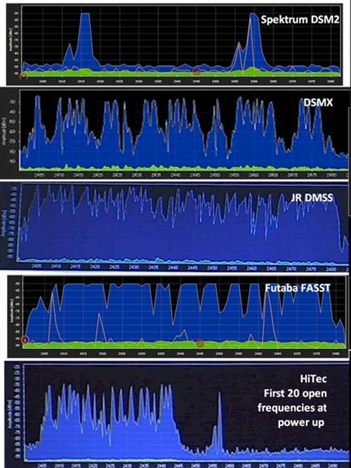
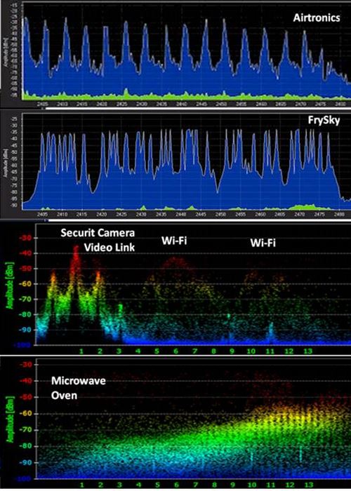
Spectrum Graph Analysis of Some Common 2.4GHz Systems & Noise Generators


Need Heli Help?
- Getting into the hobby but have no one to help you?
- Are you feeling overwhelmed & confused?
- Are you tired of wasting time seeking partial and conflicting information?
- Don't understand the maze of RC heli setup fundamentals?
- Is that sickening feeling after crashing turning you off the hobby?
- Are you simply ready to give up?
My RC Helicopter eBooks will help you with those exact problems. Grab your copies today.

Click Here For More Information

Click Here For More Information

Click Here For More Information
Recent Articles
-
RC Helicopter e Books To Help You Succeed In The Hobby
Dec 18, 25 08:05 PM
 New to the hobby? Self learning & need help? Frustrated? These RC helicopter e Books will help, while cutting your learning time down substantially.
 -
Toy Helicopters - Which offer the best value & fun in 2026?
Nov 25, 25 06:23 PM
 With so many toy helicopters on the market in 2026, which are worth your time and money? Here are my top recommendations.
 -
RC Helicopter For Kids & Beginners - Making An Informed Purchase
Nov 25, 25 06:19 PM
 How To Choose The Best RC Helicopter For Kids & Beginners in 2026


