Understanding RC Antenna Operation & Placement
by John Salt - Last Updated April 2025

"What type of RC antenna should I use and where should I mount it for a solid RF link and good range?" This is a common question that keeps popping up in my inbox.
To best choose the what and where of antennas, you must first understand the basics of how and why RC antennas work.
I'm trying to keep this article as basic as possible for the average RC'er (which I am). There will be over-simplifications & generalizations galore, plus I don't pretend to understand all the electrical physics involved in the very complex deep rabbit hole of antennas.
After all, electrical and telecommunication engineers spend their entire professional careers deep inside that antenna rabbit hole getting a handle on this stuff. Antennas are truly one of the most important, yet unpredictable components of the of RF (radio frequency) system. Therefore, the best an average RC'er can do is understand the fundamentals of RF and antennas.
With that knowledge, we can at least figure out type, where, and in what direction to position/mount the antennas; both on the RC radio and on the RC model.
I use the exact same principles I discuss on this page with my own models; which as you likely know by the name of this website, primarily consist of helicopters but I also fly EDF jets and they can get pretty far away.
 Helicopters & Jets - Close & Long Range RF Requirements
With RC helicopters, we actually have it pretty easy when it comes to RC antenna placement and orientation because even our big birds never wander that far away.
Even the big ones start getting hard to see much past 600 feet (about
200m), and most of us for legal and safety reasons, only fly helicopters
within VLOS (visual line of sight).
To be perfectly honest, us RC heli pilots rarely run into range issues that the big scale plane & jet pilots, glider pilots, and long range FPV pilots do. We (heli fliers that fly VLOS) could likely mount our antennas in less than ideal locations and orientations, and still eke out a decent RF link.
That said, I want this article to help all RC'ers, and
let's face it; wouldn't it be best to position your RC antenna on your
radio & heli to give you a rock solid RF link regardless.
For this entire discussion, I'll be using 2.4 GHz examples since that is by far the most common radio frequency in use today by most RC radio manufacturers.
How Do RC Antennas Work?
Before understanding the basics of how an RC antenna works, we should first take a peek at the electromagnetic (EM) spectrum.
This includes all the various wavelengths and frequencies of electromagnetic radiation. From very short and high energy Gamma rays, to medium lower energy wavelengths of visible light, all the way down to the very long and low energy radio waves.
 Electromagnetic Spectrum - Radio Waves On The Right
The shorter the EM wavelength (higher frequency), the more energy it has. Higher energy wavelengths beginning somewhere in the ultra-violet out to Gamma wavelengths are classified as ionizing radiation. You know, radioactive.

These very short, high energy EM waves have enough energy to strip electrons from atoms, and are therefore damaging (dose dependent) to meat servos (humans).
Cell and DNA damage is the usual outcome.
Whereas, lower energy UV and visible out to longer wavelength radiation is safe for us; radio being the very safest as its the lowest energy of all EM.
To understand RC antennas, the important part of the EM spectrum we must look at is the length of the wavelength and the frequency; both of which are related.
Radio frequencies within the EM spectrum range from around 300 GHz down to 3 kHz. The higher the frequency, the shorter the wavelength and vise versa.
Radio waves within the EM spectrum typically span from around 1 mm in length up to nearly 100 kilometers!
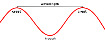
A wavelength by the way is measured from crest to crest or trough to trough of the wave as illustrated here.
Our 2.4 GHz radio system's wavelengths are about 12 cm long. Fairly short for radio waves.
Radio
frequency calculation is quite simple if you know the wavelength. Same
goes for wavelength calculation if you know the frequency. Since EM waves
travel at the speed of light, and the speed of light is a constant, (about 300,000,000
meters per second), we use this value in both these calculations. Again, I'm using 2.4 GHz examples.
Known Wavelength (0.125m) To Frequency Calculation Example
300,000,000 m/s divided by 0.125m = 2,400,000,000 Hz (2.4 GHz)
Known Frequency (2.4 GHz) To Wavelength Calculation
300,000,000 m/s divided by 2,400,000,000 Hz = 0.125m (12.5 cm)
These calculations are not important to remember, but I wanted to point out that 12.5 cm long 2.4 GHz wavelength.
This is the first thing that is important to understand when it comes
to 2.4 GHz RC antenna construction and operation.
RC Antenna Length - Mine Is Longer Than Yours
Now with all that preliminary frequency and wavelength stuff out of the way, while still trying not to venture too deep down the RF rabbit hole, we can start getting into the meat and potatoes of RC antennas.
Antennas are "resonance" devices. This means small amounts of energy (sinusoidal voltage) input, can create large amplitude outputs when the frequency of the wave, matches the natural resonance frequency of the object it's interacting with.
Most of us in the RC hobby understand physical vibrations and resonance vibrations fairly well, especially those of us that fly vibration prone eggbeaters. Well, EM frequency resonance is similar to physical frequency resonance, it's just occurring electromagnetically.
Unlike our RC helicopter resonance vibrations that we want to suppress, EM resonance in antennas is something we usually want to encourage and maximize.
I hope you can see where this is headed. Not as much energy is required to excite an antenna when the frequency of the radio wave, matches the resonance frequency of the antenna. This is what is meant by having a tuned antenna.
It's tuned specifically to that frequency so it resonates and turns a lower power radio wave into one with more amplitude (voltage).
Think of a tuned antenna as a simple, yet very effective RF amplifier.
Any antenna will transmit or receive radio waves over a broad spectrum of frequencies, but when you can tune the antenna to a specific frequency range, magic happens; nope, science happens.
Please note, this resonance tuning applies to both the transmitter antenna on our RC radio, and the receiver antenna on board our model.
A tuned TX antenna requires less power to transmit, and a tuned RX antenna is better at absorbing that EM energy. The result... Improved RF efficiency = improved range = less crashing & more flying!
So how does one "tune" an antenna?
Impedance calculations aside, the way most of us average RC'ers want to understand, is by matching the physical length of the antennas to - you guessed it - the physical wavelength of the radio wave.
As we already determined, a 2.4 GHz wavelength is about 12.5 cm (125mm) long. So our RC antennas must be 125mm long as well - right? Kinda right, or should I say, one quarter right.
You actually don't need a full wavelength long antenna to get it to resonate, any whole number fraction can also be used.
- 2.4 GHz Full Wavelength Antenna = 125mm
- 2.4 GHz 1/2 Wavelength Antenna = 62.5mm
- 2.4 GHz 1/3 Wavelength Antenna = 41.7mm
- 2.4 GHz 1/4 Wavelength Antenna = 31.25mm
- 2.4 GHz 1/5 Wavelength Antenna = 25mm
- And So On...
I've highlighted the 1/4 wavelength because in our hobby, the majority of the RC antennas we use are 1/4 wavelength types.
Beside the nice workable smaller size of a 1/4 wave antenna which fits very nicely into our models; the impedance is nice and low (shorter antenna = less impedance).
That is another topic much further down the RF rabbit hole where I care not to venture this late in the day. If you wish to learn more about 1/4 wavelength 2.4GHz antennas, how impedance dictates the amount of phase shift between current and voltage, and all the cool electrical physics involved, there is lots of great information out there. Just use your Google-Fu.
So now you hopefully know and understand why all our 2.4 GHz antennas are the length they are, and more importantly, why most of us don't, and shouldn't be messing about with the length. Also explains why when you chop just a little bit of the tip of the antenna off in a prop or rotor, your range is reduced substantially.
Speaking of chopping off the proverbial tip, that 31.25mm calculation is a generalized 1/4 wave length. The specific antenna type, impedance, shape, and circuitry within the TX or RX, also will play a part. In addition to that, most of our 2.4GHz radio systems use frequency hopping technology within the 2.4GHz band, meaning they could be jumping between 2.4 up to 2.5.
If you plug 2.5 GHz into our wavelength equation above, you'll find the wavelength comes out to be 120mm, so a 1/4 wavelength antenna would be 30.0 mm long. Yep, a shorter antenna will have a higher resonance frequency, and a longer antenna will have a lower resonance frequency.
For ease of understanding, let's just say the majority of our whisker type, omni-directional RC antennas (the ones we see on most 2.4 GHz RC receivers), will be about 31mm long, give or take several mm's as seen below.


Types Of 2.4 GHz RC Antennas
The average 2.4 GHz RC'er will be confronted with two primary types of RC radio system antennas in his/her travels.
The linear monopole, and the linear sleeved dipole.
A few common "flavors" of these two are shown below...
 "Whisker" Monopole Receiver Antenna
The most basic, common, and inexpensive type of RC antenna you can have is a single wire - that's all it is.
This as you likely guessed, this is a linear monopole. One wire, one pole.
We have
all seen these on our 2.4 Ghz RC receivers, and micro RC models. We commonly call them "whiskers".
The short piece of wire (about 31mm long) is soldered directly to the RX antenna input trace on the circuit board. If you damage one of these simple wire whisker antennas, they are easy to replace provided your fine circuit board soldering skills are up to the challenge. Just solder in another wire of similar gauge, ensuring it's the exact same length as the one you're replacing - done!
 "Whisker" Coaxial Type Monopole RC Receiver Antenna
 Coaxial RC Antenna Wire Cutaway
The other even more popular incarnation of the simple linear RX whisker monopole, consists of an extended length of shielded wire (coaxial wire), with only the center conductor at the end of the wire exposed (again about 31mm long).
Only the exposed whisker end that is not shielded will be absorbing the RF from your transmitter antenna. The added length of the coaxial monopole antenna is given to aid in both antenna placement/orientation on the model, and to improve both spacial and polarization diversity which will be covered shortly.
These coaxial monopoles are usually replaceable by purchasing replacements of the same type and are plugged into the RX circuit board by way of a tiny U.FL connector or direct soldered. Coaxial is a two conductor wire. The inner/center conductor is soldered/connected to the antenna input, and the shielded outer wiring is connected to the circuit board ground.
If just the whisker end is damaged on these coaxial type, you can repair them by just stripping some of the shielding wire away to bring the exposed inner whisker wire back to its original tuned length.
Keep Em' Straight
Regardless of a single short monopole coming direct out of the receiver, or the longer coaxial types with the antenna whisker at the end; you must try to insure the 31mm whisker end is nice and straight in your install. For a linear monopole to both transmit and receive efficiently as possible, they must be held as straight as possible.
Please note, for the coaxial whisker monopoles, the coaxial shielded section can be curved for best positioning, but the unshielded whisker antenna at the end, must remain straight.
The advantage with simple linear monopole whisker type RC antennas is they are inexpensive, light weight, and take up very little room in your model. The downside is they are inefficient power transmitters and why we generally only see them being used as receiving antennas in our hobby.

Enter the sleeved linear dipole.
These are essentially a coaxial whisker, but the shielded wire is now connected to a conductive sleeve pointing back in the opposite direction of the exposed inner whisker wire. In other words, it has two poles - thus dipole. The whisker and the sleeve are able to transmit and receive the alternating RF sinusoidal wave in both polarities more efficiently.
Most 2.4 GHz sleeved dipoles will have the whisker tuned to that 31mm or so length; the sleeve however in most I've opened up is generally several millimeters shorter. The sleeve in the example above is about 25mm long (1/5 wave perhaps?).
 RC Transmitter Sleeved Dipole Antenna
The primary application for the sleeved dipole is the RC radio transmitter antenna.
Almost every 2.4 GHz hobby grade RC radio on the market today uses a sleeved dipole. Since the transmitter is transmitting the RF as a sinusoidal wave, it needs both poles as it alternates between positive and negative voltage for improved efficiency. If the transmitter only had a monopole, roughly half the power would be transmitted. Lost efficiency...
What about at the receiver end - do dipoles make sense there as well?
Since non-telemetry RX's are
not transmitting, only receiving; there is no power loss to worry about. Some insist, a
sleeved dipole on the RX will improve receive range as well, but
I've never experienced this (to any appreciable level) myself using RSSI signal loss readings,
comparing both types in identical installs. As with all anecdotal experiences, the same weight should be given to mine - a pinch of salt.
Regardless of my experience,
I maintain the main advantage to dipole antennas on the receivers, is if the RX's are telemetry enabled and transmitting as well as receiving. Again, added efficiency when transmitting with a dipole over a monopole.
 Sleeved Dipole RX Antenna
This would be backed up by the simple fact that the first RX's with sleeved dipole's I recall seeing, were used on HiTec's Optima telemetry receivers.
Then Jeti put them on their
telemetry RX's, and other brands have been following the sleeved dipole trend on their telemetry enabled receivers.
Sleeved dipoles by the way are easy to spot over a simple monopole whisker as they will have an enlarged bulge (the metal sleeve) on the the backside of the whisker.
 Two Wire Dipole Receiver RC Antenna
Spektrum's dual wire dipole method.
Not many realize this (I know I didn't for several years), but many of Spektrum's RX's that have two wires on them (in line with each other), are in fact a single dipole, not two diversity monopoles.
You can easily tell if this is the case by opening the RX up and seeing if one of the two wires is soldered direct to ground on the circuit board, while the other is soldered to the antenna-in trace.
You can actually see this in the above photo showing the transparent backside of a Spektrum satellite RX. The wire antenna on the left marked negative, is soldered to the ground plane of the circuit board. The positive on the other side is soldered to the antenna-in trace. In effect we could remove the ground wire and still have a functioning monopole.
Another tip off here is it would make zero sense to have two separate monopole antennas in line with each other. That would defeat dual polarization diversity which we will get to shortly.
As with the linear monopole RC antennas, the linear sleeved dipole and dual wire dipole wires must be kept straight.
 PCB RC Antennas
Last up we have PCB (printed circuit board) RC antennas. There are several flavors of these things and I'm fairly new to them myself.
As they are a dipole (not really, but I'll get to that), the primary application is of course in transmitting. My FrSky Horus radio uses an internal horizontally polarized PCB antenna for example over an external sleeved dipole. There is however the option to fit an external sleeved dipole as well for dual polarization diversity which we will look at in the next topic.
The other application for them is on some of FrSky's telemetry enable RX's. If you examine the +/- antenna traces on these small PCB 2.4 GHz RC antennas, they are not configured in a typical dipole orientation, but one that more closely resembles a J-Pole which uses both 1/4 and 1/2 wave tuning. Another antenna rabbit hole to visit at your "Google" search convenience.
RC Antenna Gain, Polarization, Diversity, & Directivity
Now that we know the physical make up of our RC antennas, we have to understand how they radiate energy on the transmitter side and how they receive it on receiver side. This will help us figure out how and where to locate/position them.
Let's begin with a typical RC antenna radiation pattern...
 Polarized RC Radio Antenna Radiation Pattern
If we had a radio (TX) with a typical sleeved dipole antenna that stuck straight out the top of the radio as pictured above (vertical polarization); and if our eyes could detect RF within the EM spectrum, this might be what we would see - A big round doughnut shaped area of radio waves radiating outward all around the vertical antenna.
I'll be referring to this often as the RF Doughnut.
The strongest radio waves will be out to the sides all the way around the antenna (red in color), and the weakest (the null zone) in line with both top and bottom tips of the antenna (green in color).
This is why you want to avoid having the point/tip of your TX antenna, pointing directly at your aircraft. In that orientation it's radiating the least amount of RF energy toward your model.
That RF doughnut photo above is of course not to scale. The usable RF energy from our radio antenna is radiating outward for many kilometers, but it gets weaker and weaker the further away you go (inverse-square law).
Our little linear monopole, dipole, and PCB RX antennas are likewise listening for RF in that same big RF doughnut shape. They "hear" best along their length but not well at all out at the tips. If we use telemetry, then our little RX antennas are also transmitting in that doughnut shape and our TX antennas will be listening in the doughnut.
In short, our RF link will be:
- Strongest when both the Radio & Receiver antennas are parallel to each other.
- Weaker when they are perpendicular to each other.
- Very weak when pointed ends on, directly at each other.
If there is only one thing you
remember from this entire page, those three points are it! Knowing them will give you the best starting point for a robust RF link, to and from your RC aircraft.
Gain & Directivity
Very
simply, gain & directivity tell us how focused the transmitter antenna transmits or how
focused the receiver antenna listens. That big round doughnut shape
would be considered low gain and have a low directivity value. It's not focused at all, and radiates
fairly equally out in all directions (omni-directional), other than the two null zones out
the tips.
An example of a
very high gain, directional antenna on the other hand would be a satellite dish (dish antenna). It's
listening in a very specific narrow window of direction for the very
weak satellite signal source it is pointing at, to get every single bit of energy out of those weak EM waves.
If you have ever had to
position a satellite dish, you know just how directional they are. Just
tilting it off by a degree or so, and you can lose the signal. How do
you think it would be to fly an RC model with a high gain, directional RC antenna? Pretty hard and not practical for the average RC hobbyist.
For most normal line of sight RC radio flying applications, and to stay legal, low gain, omni-directional antennas are definitely what most of us want and need.
If our radio antennas transmitted high gain, directional waves, we could fly out further in the direction the TX or RX antennas are pointed, but range would be reduced substantially if our antenna was pointing away from the aircraft or radio. For line of sight RC flying, we are generally standing in a fixed location with our model flying all around us. For that, we want a big round RF doughnut, while we also want our models to be listening in that big round doughnut.
Some long range FPV fliers will use higher gain TX antennas on their radio and provided such antennas are always pointed out toward the direction of the aircraft, impressive ranges are gained. Regardless, the antenna/s on board the RC model must be low gain, omni-directional types. Reason being, the RC aircraft will be pointed in many different orientations while flying.
Polarization & Diversity
When talking about RC antenna polarization, we are usually referring to either vertical or horizontal. Yes there are other types such as circular; but again, I'm keeping the info here focused to our RC radio control equipment.
I've already mentioned vertical polarization, in the example of the radio shown with the doughnut shaped radiation pattern. If you recall, the antenna was sticking straight out the top of the radio (vertically). Most in the hobby will say that is not the best practice since the tip of the antenna can be pointing directly toward the aircraft when overhead and out in front of us.
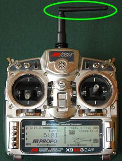 Horizontally Polarized RC Radio Antenna
The solution to this problem that many RC radios (not all) offer, is to allow you to tilt the antenna from the vertical to the horizontal... Eureka, instant horizontal polarization!
Big round RF doughnut is now on its side and no worries about the doughnut hole null zone out to the front and above.
This works well for the most part, but there is one problem, and that is when you fly far out to either side of the radio. Yep, you could now be in the RF doughnut hole null zone.
I usually pivot my body, and thus the radio to either side when flying long circuits like that to ensure the null zones are not lining up with the aircraft.
 TX Antenna Position For Good RF Link Out In Front & To The Sides
This is might be a better TX antenna orientation for some.
When tilted up and forward like this, the top tip of the antenna is pointing directly at your head while holding the TX.
Both RF doughnut hole null zones are directed up and out behind you and down forward in front.
Your melon is now in the null zone (mine is there all the time regardless of antenna orientation).
Provided you don't go flying far/high behind you, this position will still radiate strong RF doughnut out to the sides and out in front.
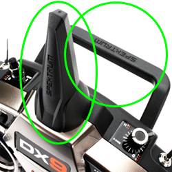 Two Antennas Provide Both Vertical & Horizontal Polarization
Another method I already touched on, is to use two antenna's, one mounted vertically and one horizontally.
Please note, most radio's have handles on the back like that, but this particular model houses an internal sleeved dipole inside the horizontal of the handle, along with one in the vertical position (both circled in green).
This dual radiation pattern if we could see it, would resemble one big RF doughnut spreading out on the horizontal plane from the vertical antenna, and another one spreading out vertically from the horizontal antenna. Complete coverage with no overlapping null zones, ya-hoo! This is called dual polarization diversity which is a nice segue into that topic.
Diversity
Antenna diversity comes in several flavors. There are two primary ones we should be aware of in our hobby: Polarization Diversity and Spatial Diversity.
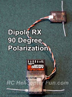
 Receiver 90 Degree Polarization Diversity
Polarization Diversity is exactly what having both a vertical and horizontal polarized RC antenna will give us.
Not only does this give a better RF radiation pattern out from the TX
antennas; when dual diversity is used on the receiver end, it improves the RX's "listening" ability in both horizontal and vertical planes as well.
Bounced and reflected signals that become
polarized can also be detected in some instances by having more than one
plane of antenna polarization. All RC manufactures suggest 90 degree dual polarization for the best results. I've always followed this myself and have never had any problems.
 Examples Of 90 Degree Polarization Diversity
Spatial Diversity is used to separate the two antennas.
Recommend distance of separation by most manufacturers is the full wavelength distance or more. So with a 2.4 GHz radio system, having the RX antennas on board the aircraft separated by about 12cm or more is a good practice if possible.
Those familiar with Spektrum, and use their satellite receivers for improved polarization diversity, also allow improved spacial diversity. There is a reason they come with with 14cm or longer wire harnesses. If you have the room and space on your model, it's best to use that entire distance up.
Any blocked or reflected RF not getting to one set of the Spektrum antennas has a good chance to be fully detected by the other with a wavelength or more of spatial separation.
There is a good deal of misunderstanding out there about diversity. Many say it gives improved RF range and that is not really true, at least fundamentally.
What dual polarization and spatial diversity give you is an RF flying environment with greater coverage, and less null zone moments. Naturally, if improved diversity minimizes "weak" spots within the RF environment you are flying, improved range within those weak areas will result; but only within those weak areas. Maximum range as a whole is not improved.
RC Receiver Antenna Placement & Orientation
Finally, all this RF and antenna stuff has (hopefully), given you enough information to now determine the best possible antenna positioning on your RC aircraft. Scratch that! There is no such thing as "best position". Let's say, best compromised position.
Let's start with the radio/transmitter antenna since it will be more or less a constant. You don't want to have to remember if one RC model works best with your TX antenna in the vertical, and another model in the horizontal. Pick one TX antenna orientation and stick with it!
I'll be using horizontal TX antenna polarization in the following position examples since it's a popular one that many people use, myself included.
Now, what about the receiver antenna/s placements and orientations? Unlike the TX antenna that is more or less being held by the pilot in that fixed horizontal orientation, our models are flying all over the place. Banking, climbing, diving, right side up, and inverted - the antennas are always pointing in different directions throughout a flight.
In addition to all that, there can be
many electrically conductive objects on today's RC aircraft that can block or reflect RF. Carbon
fiber is a big one that we have to deal with on helicopters and
quad/multi rotors. Motors, engines, ESC's, batteries, flight
controllers, etc. If it's electrically conductive it can shield RF or
reflect it to varying degrees.
Every application can be different, and what might be gained in one direction or orientation of flight, could very well be lost in another. In other words, this is all compromise and can require some experimentation if you want the best range possible.
All that said, here are some simple 2.4 GHz RX antenna points to consider which should help give you a pretty robust RF link off the bench.
- Remember the three primary RF antenna rules: Parallel Strong, Perpendicular Weak, Tip to Tip Very Weak.
- Visualize RF doughnuts with various antenna positions.
- Know your transmitter antenna polarization orientation and plan your aircraft antenna installs accordingly.
- Know your primary flight attitude you fly in most of the time (especially when far away) and position at least one of your RX antennas accordingly.
- Try to keep the antennas away from electrically conductive surfaces on your RC aircraft.
- Try to maintain both 90 degree polarization diversity & spacial separation diversity with your RX antennas.
- Don't mess around with antenna length/tuning unless you understand all aspects of antenna physics - most of us don't.
- Keep the exposed "whisker" ends of the antenna straight.
- Always Perform A Range Check.
- If
you only fly micros close in (say no more than 150 feet or so), you
will almost always have a strong RF link even with poor antenna
placements - don't sweat it!
Some RC Antenna Positioning Examples
When I'm positioning my aircraft antenna's, I guess the first thing I consider is how the aircraft will be flown in relation to the transmitter antenna position.
For example, when I'm flying
helicopters, I'll never be doing any inverted stuff while out at the
ends of my visual flying threshold (at least by choice). Any aerobatic flying, I do fairly close
and in front of me. In other words, I "usually" want my primary/best antenna placement on all my helicopters catered to upright and level flight when I need that maximum range.
 Vertical & Horizontal 90 Degree Spektrum RX Antenna Orientations
Shown above is a very typical heli antenna install with the primary antenna position being horizontal (same as what's on my radio), and the secondary position vertical for when the helicopter is tilted sideways.
The other item to note is the antennas are all out in fairly open space with no carbon directly shielding them.
 FrSky RX 90 Degree Vertical & Horizontal Polarization
As shown above, long wire whisker type antenna are often held in position using tape or RF transparent tubing (3mm air line tubing works very well or plastic antenna tubing).
I've used both tape and tubing in this particular install. Horizontal antenna is held to front tray with tape, vertical antenna is slid inside tube that has been hot glued on the top and bottom to keep it positioned.
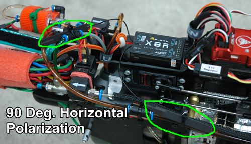
In this example both RX PCB antennas are maintaining close to 90 degree polarization diversity, but both are horizontal. There is no vertical antenna placement on this bird. Why? A perfect example of compromised antenna positioning.
This is a turbine powered helicopter, and there was just no practical way to mount one of the PCB antennas vertically due to space restrictions up top, and large amounts of shielding from the turbine engine located directly below the mounting plate.
There are also lots of electronics and the fuel systems toward the front. I had very few options and simply chose the two best mounting locations available that were fairly out in the open, not heavily shielded, and within the reach of the RX.
Thanks to RSSI telemetry, I could confirm a strong RF link afterward while flying both out far and while close, in all orientations.
A Few Last RC Antenna Words
Don't pull your hair out over all this as I sometimes see when people venture way too deep down the RC antenna rabbit hole. Keep to the basic points I listed above and don't overthink your install. Less is often more when it comes to RC antenna placement and positioning.
What I wanted to achieve here is to show you the basics of how our little 2.4GHz antennas operate along with best and worst placement practices. Chose your best "compromised" install based on that information. Experimenting and range checking afterward to make sure all your RC antenna installs give a solid RF link.
Speaking of range checking, don't overlook this very important step for any RC model. It's one of the single most important things you can do to verify a good RF link.
I'm actually amazed at how many modelers choose to ignore just how important range checking is. Check your radio manual for the recommended procedure as it can vary a bit from brand to brand.
Lastly, if
you fly with telemetry, and it monitors your RF signal strength, that
is perhaps the very best method of ensuring a solid RF link. Don't omit the simple ground range test first, but telemetry is a wonderful tool - use it if you
have it :-)


Need Heli Help?
- Getting into the hobby but have no one to help you?
- Are you feeling overwhelmed & confused?
- Are you tired of wasting time seeking partial and conflicting information?
- Don't understand the maze of RC heli setup fundamentals?
- Is that sickening feeling after crashing turning you off the hobby?
- Are you simply ready to give up?
My RC Helicopter eBooks will help you with those exact problems. Grab your copies today.

Click Here For More Information

Click Here For More Information

Click Here For More Information
Recent Articles
-
The Ultimate RC Helicopter Tools Guide: What You Need & Why
Apr 10, 26 12:56 PM
 A complete breakdown of RC helicopter tools. Let's cover swashplate levelers, pitch gauges, hex drivers and much more to help you achieve a pro-level build.
 -
Best RC Battery Charger Guide: How to Choose the Right One
Apr 07, 26 02:29 PM
 Confused by Amps and Watts? Learn how to choose the best RC battery charger with this guide covering features, power, ratings, safety and much more.
 -
RC Power Supply Guide: Don't Starve Your RC Charger
Mar 31, 26 06:33 PM
 From low cost converted server power supplies to commercial grade options, let's find the best RC power supply for your specific RC battery charger.