E-flite's Blade CX3 LED Navigation Light Kit Tips
by John Salt
")
The CX3 LED navigation light kit is a nice little upgrade to install on your CX3 heli to give it more scale appearance while flying, and yes they do just that.
I wrote this page to give you some tips on installing the navigation light kit in your CX3, but more importantly how to program a DX6i, DX7, or JR Spektrum radio to operate the CX3 navigation lights remotely while still retaining the remote gyro gain function.
There seems to be much confusion on this topic and many people think you can only have one or the other, not both. I have even heard that some hobby shop personnel are telling people you can’t control both… This is not the case at all.
First – A Little CX3 LED Background
There are two CX3 LED kits for the CX3 - the EFLH2009 and the EFLH2009R. The "R" version has the ability to be controlled from your transmitter to turn the lights on or off; plus switch between blinking or constant on for the 3 red LED’s (the white landing light LED doesn’t blink at all). The remote function also allows you to dim all LED’s down in "ON" mode only. In blinking mode, they are set to a constant brightness and blink rate.
The non remote CX3 LED kit (EFLH2009) comes on when you power up your CX3 when the battery pack is plugged in and there is no way to control the lights. Is this a big deal and do you need the remote light function?
The lights look great and you will want them on most of the time... BUT, they do eat into flight time and power output. Yup, when the lights are on, the CX3’s climb out rate is noticeably slower and your average flight time will be shortened by perhaps 30 seconds or so.
You could manually unplug the lights from the receiver anytime you don’t want them on, but it is a pain and over time, the wiring, plug, fuselage, and even the receiver can get damaged. Besides, the remote version of the CX3 LED kit (EFLH9000R) only costs about 6 bucks more than the base kit. The option of turning the lights on and off remotely is certainly beneficial and well worth the few extra dollars.
Both CX3 LED light kits use red LEDs with a small flasher chip built into each LED. You can see this small chip as a black dot inside the LED. The white LED as I mentioned doesn’t have this flasher chip and therefore won’t flash. With all 3 red LEDs using an independent flasher chip, the flash sequence between all lights is always changing – this looks much better than if all 3 were to flash in unison.
It would be nice if the flash “on pulse” could be shortened to look more “strobe” like; but that would require independent flash circuitry for each LED and add to the cost and weight. Using common flashing LEDs is a good compromise.
INSTALLING THE CX3 LED KIT
You know I am a stickler when it comes to weight increases on small micro coaxials. I must confess, I was a little worried how much extra weight would be added by the CX3 LED set and if it would throw the center of gravity (CG) out much (CG on coaxials is so critical). I was very happy to see the gauge of the wiring used on the CX3 LED kit was very small. Wiring can certainly add weight quickly, especially the long length out to the two lights in the tail boom.
After the CX3 LED kit was installed, I could not detect any change in heli performance or flight time (with LED’s turned off); so the very small amount of weight added certainly didn’t effect a thing. Keeping in mind weight is additive; if you have already added significant weight with aluminum upgrades, then the LED kit may push the weight threshold too far and really eat into flight time and RC helicopter performance.
To make the installation process go smoothly and more importantly provide a neat install, you really have to remove the fuselage. Routing the wires, mounting the small control board, and fitting all 4 LED’s will be much easier with the fuse removed. The wire lengths used on all LEDs is perfect – not too long or short. As a result, wire placement is easy and mess free.

I had to file the two holes in the tail boom slightly larger with a Dremel moto tool for the two LEDs to fit in the holes. A small round hand file will also work, but it’s easy to damage the fuselage so go slowly. After sizing the holes correctly, it was a simple matter of removing the tail boom cone and dropping the two red tail LEDs down the boom and out the end. Working them into the upper and lower holes in the boom with a pair of small needle nose pliers through the end of the tail boom was actually very easy.
The instructions say to use a dab of hot glue to hold them in place. I am sure that works fine, but again I am always concerned about added weight so I used a single drop of thick CA glue for minimum weight gain. If you use CA, be very careful and use a good method of applying the "SINGLE" drop of glue. If the glue runs inside the fuselage, it will most likely damage the inner paint finish.
The CA glue set up very fast as it wicked its way around the LEDs. I know if I crash and damage the fuselage or horizontal stabilizer fin, it will take a bit of work to remove the LEDs, but with a little cutting and perhaps sanding/grinding it won’t be too bad.

Next I installed the two LEDs in the nose. I first bent the wire leads from both nose LED’s at a 90 degree angle to allow room for the receiver and 3 in 1 unit while fitting the mechanics back into the fuselage. Each LED was then installed so the wires were directed to the right side of the fuselage since that is where the remote LED control board will be located for easy hook up to the receiver.

I mounted the CX3 LED control board between and underneath the two side window openings with a piece of double sided foam tape that came in the CX3 RC helicopter tool bag. This location allows for nice clean wire routing and doesn’t throw the CG out.
The last step was securing the wire that heads down the tail boom to the right side of the fuselage with a small piece of clear tape just behind the back window in the fuse. This is just to keep the wire secure so it doesn’t get caught up in the mechanics when you are reinstalling or removing them.
Time to refit the mechanics into the fuse. It is up to you if you wish to plug the CX3 LED lights into the AUX 1 channel of the receiver now or after you install the mechanics. There is certainly enough room through the front & rear door windows to grasp the plug with some tweezers and gently plug it into the AR6100e receiver.
PROGRAMMING YOUR DX6i FOR REMOTE LED FUNCTION
As you know from my CX3 Tips page here , I strongly encourage using the remote gyro gain function on the CX3 to fine tune the heading lock gyro gain to give a twitch free heli. The obvious question is if your gear channel is used up by the gyro, how can you now control the LEDs?
The great thing as I say many times about computerized programmable radios is how adaptable they are. This adaptability coupled with the fact that the Blade CX3 uses the 6 channel AR6100e Spektrum receiver gives the two required items to remotely operate the LEDs while retaining remote gyro gain control.
HOW?
If you are using remote gyro gain, the yellow wire from the gyro will be plugged into the “GEAR” channel on your receiver and you control it with your “FLAP/GYRO” switch on your radio. Now you still have the “AUX 1” channel on the receiver to plug the CX3 LED kit into and the “MODE” switch on the top of your radio; this is what you need to program.
In HELI configuration, the mode switch’s position plus the pitch curve values are used to control the pitch servo. The CX3 is a fixed pitch coaxial of course and this is why the pitch curve/AUX 1 channel can be used to control the LED’s. You simply have to program two straight line pitch curves; one in “NORMAL” flight mode and one “STUNT” flight mode to duplicate an “ON/OFF” switch setting as seen by the AUX 1 channel.
The following very simple pitch curves will turn the Blade CX3 navigation lights on in Stunt mode (switch position 1) and off in Normal mode (switch position 0).
Go to your pitch curve menu screen (#7 on the DX6i) and select the NORM pitch curve. Set all 5 points (L, 2, 3, 4, &H) to 100%. This will give a straight line along the top of the pitch curve graph. Now select the STUNT pitch curve and set all 5 points to 0%. This gives a straight line along the bottom of the pitch curve graph.If you want the lights to be on in normal mode and off in stunt, simply switch the curve values around in both modes or in your servo reversing menu, change PITCH from Normal to Reverse.
CONSTANT ON & DIMMING THE LED's
The CX3 LED kit turns on in normal blinking mode at 0%. At about a 30% ATV setting the red LEDs stay on constant with no blinking. As the ATV rate is increased past 30 % up to 100%, all 4 LEDs will dim down to the point where they are off at about 97%.
Now, seeing that you are using the pitch curve channel to control the remote CX3 LED kit, you can get pretty creative if you want. By changing the ATV (Adjustable Travel Volume) values within the 5 point pitch curves, you can have the lights do different things at different throttle stick positions.
For example, you could have them come on steady at low throttle and blink while flying. Another good one I started using is to have them in normal blinking mode the whole time but at full throttle, have them turn off so I still have full climb out power when I need it. The pitch curve for that kind of “auto lights off” control would be: L, 2, 3 & 4 all set to 0% and then H set to 100%.

When you give a full throttle command, the lights will automatically turn off so you have full power available for fast climb outs. You may need to adjust your throttle curve a bit for this to work. I use the following throttle curve: L=0%, 2=60%, 3=65%, 4=75%, H=100%.
There is a nice little side benefit to this “auto light off” pitch curve. Because the lights are set to turn off at higher throttle values, as your battery pack weakens during a flight, you need to keep increasing the throttle to keep flying. Once you reach the upper threshold of throttle stick values the lights will turn on steady because they are seeing an ATV value greater than 30% in that last jump on the pitch curve as the throttle stick occupies that last 25% of stick movement. This is a great visual indicator when the battery pack is almost exhausted. The lights will stop flashing and stay on steady when it is time to land.
There are so many combinations you can play around
with in both normal and stunt mode switch settings. There is also the
throttle hold pitch curve if you really want to go wild with different
light control combinations. This alone makes the CX3 LED remote
navigation light kit such an entertaining upgrade – well worth the price
and highly recommended.


Need Heli Help?
- Getting into the hobby but have no one to help you?
- Are you feeling overwhelmed & confused?
- Are you tired of wasting time seeking partial and conflicting information?
- Don't understand the maze of RC heli setup fundamentals?
- Is that sickening feeling after crashing turning you off the hobby?
- Are you simply ready to give up?
My RC Helicopter eBooks will help you with those exact problems. Grab your copies today.

Click Here For More Information

Click Here For More Information

Click Here For More Information
Recent Articles
-
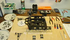
The Ultimate RC Helicopter Tools Guide: What You Need & Why
Apr 10, 26 12:56 PM
 A complete breakdown of RC helicopter tools. Let's cover swashplate levelers, pitch gauges, hex drivers and much more to help you achieve a pro-level build.
 -
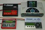
Best RC Battery Charger Guide: How to Choose the Right One
Apr 07, 26 02:29 PM
 Confused by Amps and Watts? Learn how to choose the best RC battery charger with this guide covering features, power, ratings, safety and much more.
 -
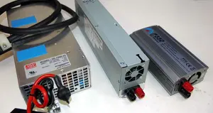
RC Power Supply Guide: Don't Starve Your RC Charger
Mar 31, 26 06:33 PM
 From low cost converted server power supplies to commercial grade options, let's find the best RC power supply for your specific RC battery charger.