How Do Model Turbine Engines Work?
by John Salt Last Update February 2026
 Wren Model Turbine Engine
The principle of how model turbine engines work or any turbine engine is very simple.
They suck in lots of air, compress it, add fuel to the compressed air, ignite the compressed air/fuel mixture, and blow it out the exhaust nozzle/s.
Basically the exact same sequence that is followed by all internal combustion engines (ICE) - suck-squeeze-bang-blow!
What is different however with all turbine engines is this is all happening continuously (called a Brayton Cycle). There are no individual SSBB cycles where power is not being produced like in a 4 stroke engine where out of the 4 strokes of the piston, only one (the bang) stroke is actually producing power.
A turbine engine is producing power all the time and is why they are both very powerful, and very thirsty.
Not only that, they compress much greater volumes of air than conventional internal combustion engines so more fuel can be added to give the same fuel/air mix ratios providing yet more power output.
Igniting this already highly compressed air fuel mixture causes it to expand very quickly and seeing that there is highly compressed air at the front of the engine, this hot expanding air takes the path of least resistance – out the back end of the engine.
As the hot expanding air exits the back of the engine, it is forced by the turbine wheel/blades. This causes the turbine to spin and since the turbine blades are connected directly to the compressor blades by means of a shaft – the compressor spins and the whole cycle starts over. In other words the entire process is self sustaining.
 Model Turbine Engine Turbine Wheel & Shaft
The more fuel that is added, the hotter and greater the expansion of gas will be, causing the turbine to turn even quicker, thus sucking in and compressing even more air. The end result is lots of hot compressed expanding air exiting the back of the engine. This turbine exhaust is converted into a high speed jet of air by forcing it through a propelling nozzle (reduced diameter outlet), and the result is THRUST!
You might be scratching your head right now thinking... "I understand all that, but how do you get this self sustained process going? If you just add fuel into the combustion chamber and ignite it, the hot expanding air will exit both the front and back of the engine - no"?
That is a great question and you are absolutely right. The engine has to be spinning fast enough to create enough of a pressure differential between the intake and exhaust (higher pressure at the front) so the hot expanding air exits out the back and past the turbine.
For model jet engines, this "pre-spinning" is accomplished by either blowing compressed air into the front of the engine by say a leaf blower, spinning the engine with an external high speed electric starter, or by far the most commonly used method these days - using a permanently installed small electric starting motor that is mounted onto the front of the model turbine engine.
This electric motor uses something called a Bendix engagement clutch so the only time it's mechanically "connected" to the output cone on the front of the compressor shaft is when the electric motor is powered up and spinning. The torque inertia from the spinning motor forces the Bendix clutch's engagement rubber friction ring to "wind up" and press/seat against the small aluminum cone on the turbine shaft and then starts spinning the compressor/turbine shaft.
Once the turbine starts, the electric starting motor shuts off and the Bendix disengages as there is no more torque inertia to keep it pressed up against the cone. This prevents the small electric motor from spinning with the turbine after it has started which would destroy the small electric starting motor considering the speeds the turbine spins (upwards of 160,000 RPM).
 Electric Starting Motor With Bendix Clutch
Centrifugal-Flow Model Turbine Engines
 Centrifugal Flow Model Turbine Engine
As you can see from this cut-away view of a model turbine engine above, most (if not all) of today's commercially available model turbine engines are of the centrifugal-flow type.
These engines use a single large centrifugal compressor blade to "throw" accelerating air outwards into the the convergence (compression) zone of the engine, which is typically called the diffuser. This design is light and provides adequate compression efficiency from a single compressor wheel.
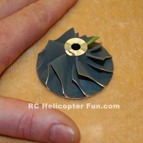 Centrifugal Model Turbine Engine Compressor - Human Paw Shown For Scale
Small, simple & light weight, with very few moving parts compared to an axial-flow compressor with multiple compression stages, compressor blades, and stator vanes to achieve much better compression efficiency (at the expense of size, complexity, cost, and weight gains). Improving compression ratios in a turbine engine has the same benefit as in any internal combustion engine - better efficiency.
This is where model turbine engines suffer...
Miniature Model turbine engines are about where the full size turbine world was back in the 1940's! In short, development of mini turbine engines is still very much in its infancy with typical efficiency numbers of only 6% or so. For model fliers, we don't really care; but just think what the future holds for the miniature turbine as these numbers slowly and steadily increase; with far reaching applications well beyond that of our hobby.
Here is good good write up on the de Havilland Goblin full size centrifugal-flow turbo jet engine. It is a good read if you want to understand more about centrifugal-flow turbines and see how similar the scaled down model variety are (there is a good cut-away photo). Other full size centrifugal-flow turbo jet engines include Rolls-Royce's Derwent and General Electric's Allison J33 which powered popular jet fighters of the day such as the Lockheed P80's, Sabb 21R, and the Fiat G80 to name a few.
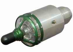
The picture below shows a Wren electric start turbo jet engine. The pod sticking out the front of the turbine encases the electric starting motor to get the turbine spinning. Also notice this engine has screening around the intake. This is to protect the model turbine engine from FOD (foreign object debris or damage).
Once the model turbine engine is spinning, only then can fuel be added to the combustion chamber and ignited. Now the next thing to realize is that in order for the fuel to ignite, it has to enter the combustion chamber in a gaseous state, not liquid.
This isn’t a problem once the combustion chamber is hot – the liquid jet fuel (kerosene or Jet A) will vaporize as it flows through the combustor tubes and is introduced to the high temperature air. It is however a problem when starting a cold engine which we will look at shortly, but first let's look at the combustion chamber and the hard job it actually has.
 Model Turbine Engine Combustion Chamber & Diffuser Sator Vanes
Shown above is the stainless steel combustion chamber / can. Gas turbine engine combustion chambers (also known as combustors) are truly amazing pieces of technology. Many turbine experts state combustors are as much "art" as they are science.
The end goal is to maintain the flame within the combustor while not allowing the hottest part of the flame to touch any of the surrounding metal.
A turbine engine combustor is essentially utilizing the the air flow around and into the combustion chamber like a magnetic field to contain and suspend the flame in the flow of air; while at the same time getting as much energy as possible out of the fuel (complete combustion). That takes lots of development and experimentation, and with our little centrifugal flow model turbines that are so short, very difficult to achieve.
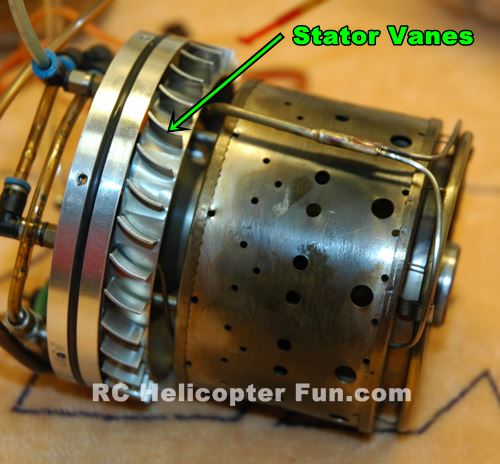
 Model Turbine Engine Diffuser Assembly
Also shown are the diffuser stator vanes. These are stationary along with the front face of the diffuser that forms a series of divergent ducts which then compress and redirect turbulent swirling compressed air from the centrifugal compressor.
Due to compression, the air is heated while the flow speed lowered, and then passes by the stators to form a relatively smooth flow of the exact correct velocity air to be introduced into the combustion chamber.
That
pressurized air flow has to remain stable, and held at the correct velocity range
to maintain combustion and cooling characteristics throughout the speed
range of the engine. The air flow must not be too fast, not too slow,
and able to maintain the correct cooling and flame length in the combustion chamber.
It's mind boggling air flow physics & fluid dynamics at work.
The way the air from the centrifugal compressor interacts with the diffuser is where most of the development time is spent when designing these little model turbine engines. Small, yet incremental improvements over years is the progression rate.
The costs of development and waste from failures are enormous! Designing and building model turbine engines is not for the faint of heart in other words; and it explains why there are only a handful of these passionate (obsessive may be a better term if you ask any of them) model turbine manufactures world wide.
If you really want to get an appreciation of what building a model turbine engine is all about, Wren released the build plans for their MW-54 several years back for the ultra enthusiastic model turbine home builder, and those just curious about model turbine engines in general. It's a great publication that will really hit home how difficult it is to successfully build one that actually works.
So while the overall operating principle of a centrifugal flow model turbine seems simple enough; there is so much depth to how they actually work, the developmental stories behind them, building one that actually works well, and why they are not cheap.
Here is a great video showing a see through centrifugal flow model turbine engine in operation.
Model Turbine Engine Cold Start Methods - Starting Gas & KeroStart
To solve the previously mentioned cold start issue, two methods are currently in use. The first method is to use propane or a propane/isobutane mixture as the starting fuel source. This "starting gas" is already in vapor form (at atmospheric pressure) so a glow plug can ignite the air fuel mixture, this gets the engine started and warmed up.

Once warmed up the propane/isobutane is turned off by the electric solenoid gas valve and the kerosene is introduced as the primary fuel source by turning on the second solenoid fuel valve and fuel pump.
The picture above/right shows the two electrically controlled starting gas and main fuel valves used in an auto start model turbine engine.
Most turbine powered RC aircraft that have auto start systems will carry some of this IsoButane/Propane starting gas onboard in a small 1 to 2 oz light weight aluminum starting gas bottle that is plumbed directly to the starting gas solenoid and may also have an in-line adjustable pressure regulator.
You don't need to put much starting gas in. A 10 second fill on my particular heli is all I need for half a dozen starts (that would likely be about a teaspoon or so in volume). Adding more than that is just a waste and it generally also produces a BIG FLAME out the exhaust on start-up due to the increase in pressure.
 Filling Starting Gas
In the photo above, I'm filling up the on-board starting gas bottle with a standard camp stove/lantern isobutane/propane mix gas bottle. You just get a special fitting for the bottle that hooks to a 3mm dia Festo hose and quick-connect that plugs into the aircraft's starting gas filler port. The gas bottle fitting I use has a simple press valve that you just press on the valve ears and it opens the valve to flow the gas.
Others will have a valve you have to turn to open. Regardless of valve type, you have to hold the bottle upside down while filling so the isobutane/propane mix exits the bottle in liquid form; very much the same way a lighter would be filled by holding the lighter butane recharge bottle upside down to flow liquid butane into the lighter.
These isobutane/propane camp fuel bottles are only about $5 bucks, and one will generally last me a couple years and easily 100 starts so it's a very minor expense considering the other costs involved in turbine flight. It's also why I'm perfectly happy with starting gas and just can't justify the hundreds it would cost to convert over to a kerostart system; but that's just me...
Here's a video of a gas start sequence after a fresh overhaul of the engine:
Kerostart Model Turbine Engines
The
other method of starting a model turbine engine is by using what is
known as a KEROSTART system. This type of starting system does away
with the starting gas and uses the main fuel source (jet A or kerosene)
to start the engine.

A small ceramic pre-heater/ignitor (Wren calls theirs a Kero-Burner seen to the right) is used to vaporize the liquid kerosene and ignite it by a high voltage electronic sparker or internal glow element.
The two main advantages to kerostart is you don't need to have starting gas making it a little more convenient, several less parts to the system, and easier (saves that 10 second or so starting gas fill step) and it sounds way more realistic.
There is no "propane
pop" on startup, but instead the all too familiar "tic, tic, tic," of
the sparker just like you would hear in a full size turbine powered
helicopter followed by the "whoosh" of the combustor coming to life and then the steady high pitch spool up of the engine.
Most model turbine engine manufacturers also have kerostart conversion kits such as pictured below.
 Model Turbine Engine Kerostart Conversion Kit
The
kit includes a new FADEC, along with a new data terminal, fuel plumbing
hardware, and of course the keroburner, which is installed where the
glow plug used to be.
The draw backs to kerostart is does cost more than the starting gas method and in cold weather can be problematic to get started but they are improving. The ceramic heating element (kero-burner/igniter) can also fail and it costs much more to replace than a $10.00 glow plug. Both systems work well so it depends on what you deem more important.
Saving a few bucks and dealing with some minor starting gas hassles, or having the convenience and ease of kerostart along with a more realistic sounding startup but perhaps run into a few starting issues when ambient temperatures are lower along with the ocasional costly replacement of a failed kero ignitor/burner).
Here's a video that shows an autostart kerostart sequence...
Now when model turbine engines were first introduced about 20 years or so ago, all this switching of fuel sources and getting the engine spinning to a self sustaining speed had to be done manually. Once started, only then would the FADEC or ECU of the day handle the fairly simple task of controlling the fuel pump to adjust the speed of the engine and monitor engine temperature.
Today's model turbine engine ECU's control everything from starting to shut down, making model turbines much more reliable and safe. This type of complete on board starting is called "auto start". It costs more than a manual start system, but makes starting a turbine engine super easy and very safe. Very few if any model turbine engines theses days use manual start systems.
Now the next hurdle is getting all this model jet engine power to spin the main and tail rotor blades on our RC heli – our next topic .


Need Heli Help?
- Getting into the hobby but have no one to help you?
- Are you feeling overwhelmed & confused?
- Are you tired of wasting time seeking partial and conflicting information?
- Don't understand the maze of RC heli setup fundamentals?
- Is that sickening feeling after crashing turning you off the hobby?
- Are you simply ready to give up?
My RC Helicopter eBooks will help you with those exact problems. Grab your copies today.

Click Here For More Information

Click Here For More Information

Click Here For More Information
Recent Articles
-
The Ultimate RC Helicopter Tools Guide: What You Need & Why
Apr 10, 26 12:56 PM
 A complete breakdown of RC helicopter tools. Let's cover swashplate levelers, pitch gauges, hex drivers and much more to help you achieve a pro-level build.
 -
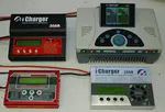
Best RC Battery Charger Guide: How to Choose the Right One
Apr 07, 26 02:29 PM
 Confused by Amps and Watts? Learn how to choose the best RC battery charger with this guide covering features, power, ratings, safety and much more.
 -
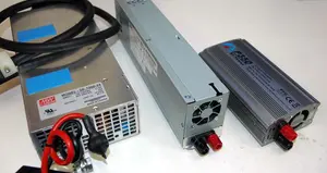
RC Power Supply Guide: Don't Starve Your RC Charger
Mar 31, 26 06:33 PM
 From low cost converted server power supplies to commercial grade options, let's find the best RC power supply for your specific RC battery charger.