RC Helicopter Rudder Control
Yaw & Anti-Torque Fundamentals
by John Salt - Updated May 2025
The RC helicopter rudder, usually called the tail rotor, makes up the last of our RC helicopter controls - specially Yaw & Anti-Torque control!
 Tail Rotor Used To Counter Both Torque & Provide Yaw Control
Let's determine how we counter torque and control yaw on our RC helicopters, along with pros and cons of various yaw control methods.
Basically what works and what doesn't, dependent on type & size of RC helicopter.
Let's start with Torque!
Torque and helicopters go hand in hand. What is torque? A nice basic description of torque is rotating force.
I think you can already see how that applies to all RC helicopters.
Helicopters have a very large rotating mechanism and coincidentally it's called a rotor. Obviously the name implies "rotation".
 Large RC Helicopter Rotor Produces Large Amounts Of Reactive Torque
RC Helicopter Rudder - Torque Reaction Control
Yes, I know, very basic stuff; but now we get back to your high school physics class - specifically Newton’s third law of motion.
You know the one that states "For every action there is an equal and opposite reaction."
It's pretty easy to understand how this law applies to all helicopters. That big rotating rotor is creating a lot of torque reaction, which I call "reactive torque" that occurs in the opposite direction of main rotor rotation.
Therefore, if our main rotor is spinning clockwise, our helicopter wants to spin counterclockwise.
This reactive torque is not consistent either; it's always changing. Any change in the main rotor speed (RPM), or change in rotor blade pitch angle (collective) will produce corresponding changes in torque reaction.
Basically, the more drag (the more the main rotor blades "bite" into the air), the more reactive torque is produced. This drag is not affected only by rotor speed and pitch angle, but also dependent on factors such as size/shape of the rotor blade and the number of blades on the rotor head.
Tri or multi blade rotor heads for example, will generally produce more reactive torque when compared to a two bladed rotor head because they produce more drag; given the same rotor speed, pitch angle, and size of blades.
 Tri-Blade Rotors Generally Produce More Torque Reaction Than a Two Blade Rotor of The Same Size, Speed, & Pitch Angle.
There are basically three ways helicopters deal with this constantly changing reactive torque:
- Tail Rotors
- Coaxial / Contra-Rotating Main Rotors
- NOTAR
1. Tail Rotors
 Variable Pitch Tail Rotor
The most common way to counter the main rotor torque reaction and yaw (turn) the heli left & right, is by using a tail rotor.
In our hobby, 2 bladed tails are by far the most common, but you will see 3 and even sometimes 4 on some scale RC helicopters.
The tail rotor is simply a propeller that produces thrust in the opposite direction to the reactive torque produced by the main rotor.
The idea is for the thrust coming off the tail rotor to equal the amount of reactive torque to keep the helicopter from spinning around.
 Fenestron Tail Rotor
Another type of tail rotor is known as the Fenestron (derived from the Latin word fenestra for window).
This is essentially a multi bladed, variable pitch, ducted fan tail rotor housed in an oversized vertical tail fin assembly.
It is rarely seen on RC helicopters due to the added cost, weight and complexity; along with cross wind challenges, over that of a traditional tail rotor.
In full size helicopters, the main reason fenestron tail rotors are used is for safety.
Statistically, one of the most common injuries around full size helicopters is from people accidently walking into the spinning tail rotor, often resulting in a fatality .
If you've ever been around a full size helicopter while its running, you know the spinning tail rotor can become totally invisible in certain light conditions. A fensestron does away with that potential danger.
The other safety benefit is to the helicopter tail rotor itself. It's less likely a tail/boom strike will cause tail rotor damage on a fenestron. Tail rotors getting caught in power lines, guy-wires, etc. is also much less likely with a fenestron.
For our RC hobby however, the reasons to have a fenestron is because they look cool and they are more challenging to build, maintain and fly. It has always been a long time desire of mine to eventually build a scale heli with a fenestron tail.
2. Coaxial & Tandem Main Rotors
 Micro Coaxial RC Helicopter Uses Counter Spinning Blades To Provide Anti-Torque & Yaw Control.
 Coaxial Rotors Cancel Torque From Each Other
The second method an RC helicopter rudder control is by using two counter rotating rotor blades. Often called "coaxial" or "contra-rotating".
They can be either be stacked on top of each other as shown in this photo, or placed a distance apart on the helicopter.
You'll find this type of torque & yaw control on most micro electric RC helicopters and toy helicopters.
It's called coaxial or contra-rotating because the rotors are each rotating in opposite directions, and thus the reactive torque from each is canceled out.
On small fixed pitch coaxial RC helicopters, yaw control is achieved by simply spinning the top and lower rotor at different speeds to each other.

Two electric motors are used to spin each blade. If one motor is slowed down slightly and the other sped up, there is a corresponding reduction of torque reaction produced by one of the rotors and and increase in torque reaction from the other - heli will turn. This makes yaw control simple & inexpensive, yet very effective.
Coaxial rotors on small micro RC helicopters are also very efficient because there is no tail rotor to power; 100% of the power is going toward lift. This improved efficiency gives most micro coaxial substantially longer flight times than similar sized single rotor helicopters with a tail rotor.
 Tandem Rotor RC Helicopter
Using two completely separate rotor systems spinning in opposite directions to cancel out the torque of each are seen on Tandem Rotor RC helicopters. These are not at all common in our hobby due to the added cost and complexity, but they do exist. Generally being custom built by true RC helicopter enthusiasts.

There are a few micro coaxial tandem rotor RC helis on the market, but they are basically using a pair of coaxial rotors. The torque cancellation on them is coming from the stacked coaxial rotors, not the fact there are tandem rotors spinning in opposite directions.
3. NOTAR
 NOTAR Tail Boom With Adjustable Thrust Nozzle
The third and least known way of yaw & torque control on helicopters, full size and RC alike, is called NOTAR (no tail rotor).
This system uses air pressure created by an internal ducted fan inside the main body of the helicopter.
This pressurized air is piped down an over-sized tail boom and released out slots that run down the length of one side of the boom, along with an adjustable thrust nozzle at the back end of the tail boom.
The air flowing out the side slots in combination with the downwash of air from the main rotor produces an area of low pressure on one side of the boom (coanda effect) to counter the reactive torque. Basically the boom acts like a big fat airfoil that provides some sideward lift (like a sail) in the opposite direction of the main rotor torque.
The rotating nozzle at the end of boom is used to throttle some of the pressurized air out the end of the boom to control yaw thrust.
When the nozzle is wide open, maximum air thrust exits the boom and the heli will yaw against main rotor torque. When the nozzle is closed, the heli will yaw with main rotor torque. When the nozzle is somewhere in the middle, a state of equilibrium between boom thrust and main rotor torque occurs - no yaw.
Here's an example of an RC MD520N NOTAR model by Scale Plus Models out of Germany. Watch for the nozzle movement at time 0:15. The nozzle is controlled by the tail servo hooked up to the tail gyro just like a conventional tail rotor.
Like the fenestron tail rotor, NOTAR designs are used to improve full size helicopter safety, but their primary benefit is producing much less noise over a conventional tail rotor or even a fenestron tail rotor.
Due to these benefits, full size NOTAR helicopters are mainly used in congested urban flying enjoinments.
Tail Rotors Are By Far The Most Common RC Helicopter Rudder Control
Most helicopters use tail rotors to control yaw, RC and full size alike. The main reasons for this? Tail rotors are simple, efficient, relatively light weight and they work well.
In our RC helicopter world, there are two ways to power the tail rotor and adjust the amount of thrust they produce.
You have to be able to adjust the amount of thrust coming off the tail rotor because as we learned earlier, the amount of reactive torque from the main rotor is always changing. The other reason is so we can turn (yaw) the helicopter in both directions (left and right).
1. Controlling Tail Rotor Thrust With Pitch
 Variable Pitch RC Helicopter Tail Rotor
This is the most common method of tail rotor thrust control, at least on larger RC helicopters.
The tail rotor gets its power from the main engine or motor of the helicopter. By means of gears, some of the power going to the main rotor is diverted down the tail boom by using a drive shaft (usually called a torque tube) or a long rubber toothed belt (belt drive tail).
This power is then used to drive the tail rotor shaft through a simple right angle gear box usually using two umbrella gears. The RPM of the tail rotor is dependent on the engine/main rotor RPM which is more or less constant, greatly minimizing speed change induced torque spikes.
In general, the tail rotor on most RC helicopters with variable pitch tail rotors will turn about four and a half times for each single revolution of the main rotor (a 4.5:1 ratio).
We control the amount of tail rotor thrust by changing the pitch or angle of attack of the tail rotor blades.
The tail rotor is
basically a variable pitch propeller that can vary the amount of right & left thrust to yaw the helicopter in either direction. With just the right amount of pitch, it provides the correct counter thrust to maintain a state of equilibrium between the main rotor torque and the tail rotor thrust so the heli will not spin / turn.
 Lots of tail rotor pitch overcomes main rotor reactive torque and heli turns right.
If lots of pitch is applied, more thrust force from the tail rotor is produced than main rotor torque force and the helicopter turns against the main rotor reactive torque.
The picture to the right shows a large amount of tail rotor pitch blowing air to the right, thrusting the tail to the left causing the heli to turn/yaw to the right.
 Little tail rotor pitch - heli turns left with main rotor reactive torque.
If we decrease the pitch of the tail rotor to the point where it is not producing much thrust to counter act the main rotor torque, the helicopter turns in the direction of the main rotor reactive torque.
This picture illustrates a left helicopter control tail rotor command.
There is very little pitch and next to no side thrust.
The heli will turn to the left due to the reactive torque of the main rotor not being canceled out by the tail rotor.
Advantages of variable pitch tail rotors:
- This is what all full size helicopters use.
- Instant tail rotor thrust changes occur with no delay.
- Very precise thrust control resulting in excellent tail hold and yaw authority / consistency.
- Must be used on 300 size and larger RC helicopters if you want good anit-torque tail hold and yaw control.
- No tail motor to burn out or fail.
Disadvantages of variable pitch tail rotors:
- More moving parts than fixed pitch so parts count is up, complexity is up, weight is up, and maintenance is up.
- Don't work well on micro/small RC helicopters because pitch parts become too tiny and fragile to last and are a pain to work on.
- Tail gyro gain needs to be adjusted for different main rotor head speeds since the tail rotor speed is a direct ratio of main rotor head speed. This is why remote tail gain is usually used on collective pitch helicopters with variable pitch tail rotors so the tail gyro gain can be automatically changed when the pilot switches to a lower or higher main rotor head speed.
The video I made below goes over RC helicopter tail rotor operation in more detail covering:
- Direction Of Rotation
- Correct Blade Position
- Pitch Slider Direction
- Tail Gyro Correction Direction
2. Controlling Tail Rotor Thrust With Speed
 Fixed Pitch Tail Rotor Direct Driven By Brushless Electric Motor
The other method of tail rotor thrust control is by using a dedicated electric motor to spin a fixed pitch tail rotor.
This method is very popular on micro and small RC electric helicopters, but never used, successfully anyway, on larger RC heli models.
Instead of getting power from the main engine/motor, there is a small electric motor at the end of the tail boom that spins the tail rotor.
Because the speed of the motor is controllable, there is no need to use a variable pitch tail rotor to change the amount of thrust.
The thrust force can be controlled by simply speeding up the motor to create more thrust or slowing it down to create less thrust.
Note, motor driven fixed pitch tail rotors never reverse direction to change thrust, they rely on main rotor reactive torque to yaw the heli one way, and thrust direction from the tail rotor to yaw the heli in the opposite direction (similar to our NOTAR example above).
I mention this because I get so many question from people new to the hobby thinking there is something wrong with their helicopter or tail rotor motor because it only spins in one direction. Nothing wrong, that is exactly how they all work.
Advantages of fixed pitch motorized tail rotors on micro/small RC helicopters are:
- Less weight (no tail rotor servo, pushrod and pitch mechanism).
- No complex gearing, drive linkages and tiny fragile pitch components so parts count, complexity and maintenance are reduced substantially.
- Fixed pitch motorized tail rotors on micro and small helicopters are simply more robust, cost effective and work better.
- No need to worry about remote tail gyro gain adjustment at different head speeds since the tail rotor speed is not fixed to the main rotor speed.
- Brushless direct drive tail motors have crazy fast acceleration rates, producing fantastic tail hold, even with violent torque changes from the main rotor.
Disadvantages of fixed pitch motorized tail rotors are:
- Tail rotor control and holding ability can be poor if the heli is too big or the wrong type of tail motor is used.
- Brushed tail motors can fail often.
The larger the RC helicopter is, the less effective fixed pitch motorized tail rotors perform due to the increase in spinning inertia; ie. the tail rotor can't respond (speed up & slow down) fast enough to change the amount of thrust to precisely yaw the helicopter or keep the tail hold locked.
Yaw control eventually becomes vague, delayed, twitchy and tail blowouts (where the tail rotor thrust is overcome by main rotor torque) become common.
 Iron Core Brushed Motor With Gear Driven Fixed Pitch Tail Rotor = NO GOOD!
Another caution is the use of conventional iron core brushed electric tail motors. They are rotten and you should avoid them at all costs; especially the ones like shown here with gear reduction. If you see a tail motor with a gear - run away!
These types of brushed heavy inertia iron core motors are also under enormous stress and therefore burn out quickly in tail rotor applications, both direct driven and gear driven.
Thankfully, these types of iron core brushed motorized tail rotors are not common anymore, but a few examples still exist so you should be aware of them and know to stay away from them.
Stick with direct drive (no gearing) coreless and brushless tail motors only!
 Direct Drive Coreless Motors & Fixed Pitch Tail Rotors Work Well On Micro Sized RC Helicopters
Coreless direct drive tail motors work quite well on smaller, 100 size micro helicopters such as XK's line of micro collective pitch helicopters like the K100, K110 & K120.
This is because the tiny direct drive coreless motor (which has very little spinning mass) direct driving (no gear reduction) a small fixed pitch tail rotor can both accelerate and decelerate fast enough to provide decent tail hold when the heli is small & light weight.
As they are not being "over worked" on 100 size micro size helicopters, these little coreless motors also tend to have fairly long lives.
Coreless tail motor failures however, even with this small size are still one of the biggest complaints. Most people who have helis such as these generally keep a spare coreless tail motor on hand for replacement.
If you fly often, it's not a matter of if a coreless tail motor will fail, but when, consider them a consumable item.
 Brushless Direct Drive Tail Rotors Work Great!
Powerful direct drive brushless tail motors such as on the Align 15T, GooSky's S1 & S2, OMP Hobby's M2 & M1 and most of Blade's smaller helicopters speed up and slow down very quickly giving impressive thrust control rivalling variable pitch.
Brushless motors also last a very long time, even when under such demanding workloads and I've personally never had to replace one (yet).
The tail hold with a direct drive brushless motor on these micro size helis is outstanding! It's all but impossible to get a blowout to occur, even when trying hard to induce one. Yaw control is precise, there can however be some minor variation between left and right yaw rates.
I often get asked what is the largest size heli that a fixed pitch, motor driven tail can work well with.
There is no one specific size generalization because as we have already discussed, there are several variables involved including tail rotor motor type, weight of the heli (amount of inertia the tail has to overcome). Along with main rotor size, shape, rotational speed, and number of blades, which all affect the amount of reactive torque produced.
With that said, it has been my experience that brushless direct drive tail motors can work well on micro to small helicopters up to absolutely no larger than 250 size (spinning 250mm main rotor blades).
Coreless direct drive motors work well up to about 120 size (spinning 120mm main rotor blades).
Conventional brushed iron core (not coreless) direct or gear driven tail motors don't work well regardless of size - stay away from them!
Full Size Helicopter With Electric Tail Rotor
 The Bell 429 EDAT Uses 4 Fixed Pitch Brushless Motor Tail Rotors.
Even though this is full size, I have to make mention of Bell's prototype 429 EDAT (Electrically Distributed Anti-Torque system) to illustrate how model RC helicopter technology has jumped over to full size. Perhaps one day, this concept will jump back over to our larger RC helicopters?
The Bell 429 EDAT uses 4 brushless motors powering 4 fixed pitch tail rotors in a quad fenestron arrangement. 4 smaller fixed pitch tail rotors are used over a large single one for the same reason discussed above: Too much spinning inertia with a single large tail rotor to speed up and slow down fast enough to counter torque and provide precise yaw control.
Electric power for the four brushless motors is generated by two generators driven off the former tail rotor output shaft from the main rotor gearbox.
Bell Helicopter lists the primary advantages of EDAT being, improved efficiency, reliability and redundancy, as well as reduced noise and lower maintenance costs compared to a traditional tail rotor.
What Is A Tail Gyro & Why Do We Need It?
By now, you can appreciate that tail rotors be they variable pitch, fixed pitch, conventional or fenestron, work very well at counteracting the reactive torque from the main rotor while also producing the precise thrust changes to allow us to turn/yaw our helicopters left and right.
There is just one problem...
Remember that the torque from the main rotor is constantly changing. What do you think that makes controlling the tail rotor like? If you said “almost impossible”, you understand this process very well.
Moreover, unlike larger full size helicopters, our smaller RC helicopters can produce violent and lightning fast reactive torque variations with collective pitch adjustment or weathervaning in fast backward flight. This is yet another reason why RC helicopter control is so challenging.
Enter the amazing tail gyro!
 The Tail Gyro
Thankfully we have the humble little tail gyro to help us out; and boy do they help!
The tail gyro will detect all these sudden and unwanted yaw movements, be they generated from torque variation, wind or weathervaning, and send the required adjustments to the tail rotor much faster than any human meat servo could.
In fact, they detect and correct in less time than most of us could even begin to see the start of unwanted yaw movement. In other words, we don't even know they're occurring.
If you really want to appreciate how much workload the tail gyro is handling, try just to hover without one or by turning it off lowering the gain to zero. I have tried and I consider it almost impossible. Small RC helicopters - forget it! Large ones, very difficult and not fun.
With the introduction of Flybarless systems, the tail gyro is now built in the flybarless unit along with the two cyclic gyros.
Understanding Tail Rotor Translating Tendency (TRTT)
I have just one more interesting item to note regarding tail rotors. It's something you'll likely notice and question when performing your first solid hover; which I also cover on day 4 in my flight school section.
Because the tail rotor is pushing/thrusting sideways to counteract the main rotor torque, the heli has to be trimmed out to have a little bit of right or left cyclic to counter the sideways thrust of the tail rotor.
For example, if our tail rotor is blowing air out to the right, thrusting the tail to the left to counteract the torque from a clockwise rotating rotor blade, this thrust will also be pushing the entire helicopter to the left.
The full size helicopter term for this is called left tail rotor translating tendency (LTRTT). To balance this out back into a state of equilibrium, a little bit of right cyclic has to be applied to compensate, so the helicopter doesn’t continue drifting left.
This can either be done by dialing in a little right or left cyclic trim, mechanically adjusting the swashplate to tilt slightly, or is done automatically by the flybarless system gyros.
You will also learn when taking off on level ground, just as you are getting light on the skids and about to lift off, most of us will apply a little bit of left or right cyclic to prevent the helicopter side slipping from tail thrust the moment it leaves the ground. Once airborne, the heli can lean slightly so we can re-center the cyclic stick.
I only mention this because a
lot of people will notice their RC helicopter is tilted slightly to the
right with a CW spinning main rotor or tilted left with a CCW spinning main rotor when in a stationary hover. The smaller and lighter the heli in relation to the amount of tail thrust produced, the more pronounced the lean will be.
Many will think they have set something up wrong or the heli is out of balance. This is not the case at all; your helicopter is doing what it has to in order to balance out all the various forces acting upon it to remain in a state of hover equilibrium.
 Micro heli leaning slightly right (when viewed from behind) while hovering to counter left tail rotor translating tendency
RC Helicopter Rudder Control Conclusion
Out of all the RC helicopter controls that have been discussed in the Theory and Control section; RC helicopter rudder control is usually the easiest to understand. It also requires the least amount of concentration from the heli pilot thanks to the tail gyro.
I'll conclude this page with a couple videos. First is one I made of basic maintenance to a variable pitch tail rotor. It may help you understand the operation of a variable pitch tail rotor better if you can see the various components and how they interact.
The next video is a good "full size" helicopter controls torque video. The exact same principles apply to our smaller model variety. If you look closely at the full size helicopter (R22) in the video, you will even see the slight lean caused by tail rotor translating tendency cyclic compensation.


Need Heli Help?
- Getting into the hobby but have no one to help you?
- Are you feeling overwhelmed & confused?
- Are you tired of wasting time seeking partial and conflicting information?
- Don't understand the maze of RC heli setup fundamentals?
- Is that sickening feeling after crashing turning you off the hobby?
- Are you simply ready to give up?
My RC Helicopter eBooks will help you with those exact problems. Grab your copies today.

Click Here For More Information

Click Here For More Information

Click Here For More Information
Recent Articles
-
The Ultimate RC Helicopter Tools Guide: What You Need & Why
Apr 10, 26 12:56 PM
 A complete breakdown of RC helicopter tools. Let's cover swashplate levelers, pitch gauges, hex drivers and much more to help you achieve a pro-level build.
 -
Best RC Battery Charger Guide: How to Choose the Right One
Apr 07, 26 02:29 PM
 Confused by Amps and Watts? Learn how to choose the best RC battery charger with this guide covering features, power, ratings, safety and much more.
 -
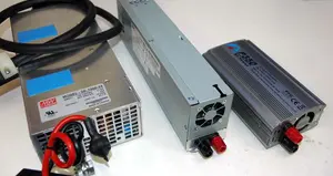
RC Power Supply Guide: Don't Starve Your RC Charger
Mar 31, 26 06:33 PM
 From low cost converted server power supplies to commercial grade options, let's find the best RC power supply for your specific RC battery charger.