HP Server DPS 600PB Build Procedure
by John Salt - Updated November 2024
 HP Server DPS-600PB Power Supply Converted For RC Charger Usage
This DPS 600PB build article is a direct result of many questions I've been getting asked recently due to Mike over at 2ZO-RC, reluctantly deciding to discontinue making his wonderful "modular" 12V 575W power supplies (PS).
As you may know from my RC power supply page, I highly recommended his power supplies since I didn't have the time or desire to convert my own server power supplies into ones for RC use. Mike's were very well priced, and a great/best option for many.
Well, with them no longer being made, we now have to build them ourselves. That's what this page is all about - how to convert an HP Server DPS-600PB power supply into one that can be used to power our current and voltage hungry RC battery chargers. Along with the modular feature for future growth or increasing output (voltage, current, or both).
These instructions are not applicable to any other model of PS. This page only covers the HP DPS 600PB build; although there are no doubt electrical similarities between other models and brands.
Before getting to the build, I have to state the obvious.
These server power supply modifications involve some basic electrical understanding and skill. They are not hard or difficult to convert, but you still have to understand the basics, know what you doing, and have the skills to pull it off (soldering being one of them).
In short, you perform these modifications at your own risk. I will not be held responsible for any train wrecks along the way.
If you doubt your ability to perform the following procedures, get someone with more electrical experience to help you.
Let's get to the DPS 600PB Build...
What's Involved In A DPS 600PB Build?
Converting server power supplies for RC charger usage is nothing new. A little searching on the web will produce lots of information on the topic.
My particular build instructions here are based on my own 2ZO-RC
converted supplies, showing you the exact same build procedure and
method that Mike used.
A very elegant, efficient, and safe conversion in other words.
Most
importantly however is how these supplies are made "modular" allowing
you to hook them together in either series to increase the voltage or in
parallel to increase the current.
It's actually not hard, but you do have to understand what you are doing. Even better if you understand why you are doing it.
The main problem with using any server power supply as an RC power supply is to first get the things to turn on when powered up. Most require a switched signal from the server/computer before they will power on.
Next is to isolate or "float" the circuit board negative/ground so you can safely hook several up in series to increase the voltage output if you so chose; while still maintaining an "earthed" referenced ground voltage at the negative output terminal going to your RC battery charger.
I can't stress that safety point here enough. YOU MUST HAVE AN EARTH GROUND REFERENCE VOLTAGE @ THE PS's NEGATIVE OUTPUT TERMINAL GOING TO THE RC BATTERY CHARGER.
Lastly is to come up with some safe & convenient way to plug our chargers into the power supply/s or to hook the PS's together. Most if not all server power supplies come with what is known as a "Hot-Swap" terminal.
 DPS 600PB Hot Swap Terminal
This is just an industry name for the dedicated power plug and pin-out connectors that allow quick and easy field replacement of these units by the technician. It's as simple as sliding out the bad power supply and plugging in the new one.
There are methods to use/maintain these custom hot swap terminals for RC charger connectivity, but
they are not exactly what I consider elegant or particularly safe.
That said and by all means, if you want to keep the hot-swap terminal on your DPS 600PB build, you can solder output wires and jumpers direct to it. If that is what you want to do, you will likely want to search for other web pages / forum posts for those particular procedures.
This DPS 600PB build I'm showing uses a 4mm dual socket terminal (4mm heavy duty speaker terminal to be exact). These dual socket terminals are ideal as they allow for both 4mm banana plugs (what is standard on most RC chargers), along with 1/4" fork connectors for hooking the supplies in series, parallel, or to earth ground the negative terminal (which is covered later on).
I highly recommend you look over my Power Supply Page where I talk all about the 2ZO-RC power supplies. It's pointless to convert one or more of these supplies for RC usage if you don't know how to use them safely with your particular charger afterward. Here are the original 2ZO-RC DPS 600PB instructions as well that may help you understand their operation better.
The DPS 600BP Build Consists Of Six Basic Steps:
- Open Up The Power Supply
- Remove The Hot Swap Terminal From The Internal Wiring & Power Posts
- Circuit Modifications (ground isolation & ribbon cable rework)
- Build & Hook Up A +/- 4mm Terminal Block
- Reassemble The Power Supply
- Make Up A Removable Ground Terminal Strap/Tab
Parts Needed For A DPS 600PB Build
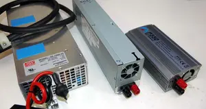
 Main RC Power Supply Build Parts
The three main parts you will need is the surplus DPS 600PB power supply itself, a power cable for it, and some sort of 4mm banana/speaker terminal.
You can find lots of surplus DPS 600PB's on eBay for very reasonable prices (some low as $20 bucks)! Amazon as well, but prices tend to be higher. Many sellers sell multiple units as well for even better pricing if you need more than one. All depends on your PS supply needs which I discuss in depth on my PS page.
 Close Up Of DSP-600PB Product ID Sticker
Shown above is the specification ID sticker on these server power supplies for anyone who wants to study the specifications.
Most of these supplies don't come with a power cord so you may need to get the cord as well. That said, they use familiar IEC320 C13 plugs. These are also called computer power cords since they are very common on computers and other electronics, so you likely have several of these spare power cords lying around your home/shop already.
Next up is some sort of +/- (red/black) 4mm banana/speaker terminals. There are various ways to accomplish this, but I like the insulated dual polarity block type.
They allow both plugging in of 4mm banana plugs (common on most RC chargers), while at the same time allowing you to fit a 1/4" fork connector for hooking them up in series or parallel, and for fitting the negative to earth grounding tab/harness.
As the block is fully insulated, you can mount it directly to metal, without any shorting hazard. Totally your call on what type connection you want to use of course.
The only other few parts you need, you likely already have lying around.
Some wire, some heat shrink tubing, some eye crimp connectors, and a small length of 3/4" 1/16" thick aluminum angle bar / similar item.
This is used for the 4mm dual terminal mounting plate which I'll show in the build DPS 600BP build below.
Any form of plate material/method could of course be used.
Tools needed include soldering iron/gun, solder, wire side cutters, wire strippers, screw drivers (phillips & flat), and a willing set of human paws.
Hot glue gun/epoxy/silicone sealant might also come in handy.
Got your parts - lets get to the DPS 600PB build!
Step 1. Opening Up The Power Supply
This is the easy part, only 10 screws to remove. If you find this part of the build difficult, better walk away right now...
 5 Screws On The Left Side To Remove
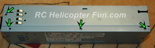 4 Screws On The Top To Remove
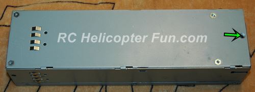 One Screw On The Right Side To Remove
 Opened Up... Success!
 Back Of DPS 600PB PS
Your DPS-600PB may also come with a pull handle on the back along with a sprung plug catch.
These can also be removed if you wish. I see little use to keep either on, but it's up to the individual.
Step 2. Remove Hot Swap Terminal
Sorry, I don't have any photos showing removal of the hot swap terminal because it was already removed on my particular PS here.
The hot swap mounting board has two screws, a nut, and two more screws that attach it to the positive and negative power posts inside the PS. Remove them all, but keep all 4 screws, you'll be reusing them with the modifications later on.
There is also a blue and purple wire going the hot swap terminal circuit board along with a 10 conductor ribbon cable. Unclip the ribbon cable plug at the hot swap board and just cut the blue and purple wires. The photos to follow will show these two wires and ribbon cable in more detail so you know where to cut them.
Step 3. Circuit Modifications
 Fan Plug Location / Removal
After your DPS 600PB is opened up and the hot swap terminal removed, I like to unplug the 3 pin brushless fan connector so that the top plate with fan assembly can be set aside.
There is usually some white mastic holding the plug in place - it just comes off/chips off usually when the plug is "gently" pulled out of the connector. If the mastic "blob" doesn't chip/fall off, gently persuade it off with a hobby knife/similar.
You don't have to remove the fan plug/top plate, it just makes it much easier to perform the modifications with it out of the way I find.
 Main Modifications To The Wiring/Board
Okay, now it starts getting fun! As shown in the above photo, cut the blue and purple wires that went to the hot swap terminal fairly flush to the circuit board. They are not used.
Next remove (desolder) the two grounding jumpers. These can simply just be cut off as well with side cutters.
Lastly is to remove the DC circuit board ground to case earth grounding screw and insulate the back side of the board from the mounting pin underneath. This step is required to "float" the negative output of the entire power supply enabling you to hook multiple supplies up in series to increase the output voltage.
Please note: The metal case will still be earth ground by way of the ground wire going to the mains - we are only floating the PCB (circuit board) negative output from the case, not the case itself from earth ground.
If you only need to use one supply (12V @ 575Watts), and never plan on hooking two or more up in series, you don't have to do this.
This "floating" can be accomplished with some electrical insulating card. A small piece cut from the bottom front of the supply where the hot swap board was works well. A small length of heat shrink folded a few layers thick underneath also works. Use some hot glue, epoxy, or RTV silicone to hold the insulation in place afterward - you don't want that insulation to ever come out of position!
You don't need a screw in there as it's not absolutely necessary to have that corner of the circuit board mechanically attached to the case of the DPS 600PB. It's not like we are going to be launching this thing into orbit (intentionally anyways) ;-)
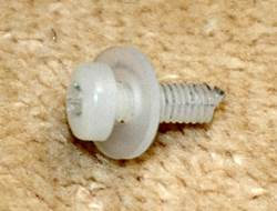
If you still want a screw in there, Mike's solution was to use a nylon M3x8mm insulating screw with an insulating washer on the front and back side of the board.

As he was building these things for selling & shipping to the public, it makes good sense he wanted to take that extra step of keeping the board securely attached to the case, while still having it insulated.

If you really want to play it safe after you finish insulating the board from the case and cutting/removing the two grounding jumpers; check for any continuity afterward between the circuit board and the case with a digital multi meter. You could also check between the case and the negative output post/terminal. You want to see infinite resistance!
Now we have to mod the ribbon cable. Start by cutting off the plug on the end of the cable.
Next, divide the cable in half (5 conductors on each half).

10 conductor ribbon cable divided in half (5 conductors on each half).

Divide and strip some insulation off the first 5 wires (the outer most wire is red), twist, and solder them together. These 5 wires will be hooked to a DC ground. They tell the power supply to turn on, set the output voltage at 12VDC, and set the fan speed to low while still allowing the fan to automatically ramp up speed in relation to internal temperature and higher demand loads.
The remaining 5 wires (conductors 6-10) are not used.

Now solder a short length of wire to the 5 ribbon wires you just twisted/soldered together.

Insulate that connection with heat shrink.

Use another piece of heat shrink around the first to insulate and secure the unused 5 ribbon wires.

Finish up by soldering that single ribbon ground wire to the right side of the jumpers that were cut, or direct to the circuit board if you desoldered those jumpers. Doesn't matter if it's the front or rear right jumper trace, both are electrically connected.
This point is also electrically connected to the negative power post located directly behind it so you could also hook that wire to the negative post if you found that easier.
Step 4. Dual Terminal Block Connection & Installation
 DPS 600PB 4mm Dual Terminal Block Mounted To 3/4" 1/16" Thick Aluminum Angle Bar
As shown in these images, the dual terminal block build is both simple and compact.
You have to make up a couple lengths of wire to hook the terminal block to the main power pins on the circuit board.
I use 12 AWG wire for this with an eye terminal crimped on each end (one end to mount to the terminal block posts, and the other to the power posts in the PS).
Next is the plate to mount the dual terminal to. There are many options here so use what method you like best. Mike's simple and elegant approach was to use some 3/4" wide x 1/16" angle bar cut to 5.5 cm long. This stuff is easy to find at most home building centers (Home Depot for example), but chances are you likely have something lying around that will work just as well.
The angle bar allows easy attachment using the two threaded inserts that are already in the bottom of the supply. Use the two screws you saved that held the hot swap circuit board in place for mounting this angle rod.
The two large holes for the dual terminal block are 1/2" in diameter and 19mm on center to each other. Drilling 1/2" holes with a drill bit in soft 1/16" aluminum is not exactly easy. I found it much easier to first drill a smaller hole and then use a round file to enlarge it/them to 1/2" and make sure they are positioned correctly. A stepped drill bit would most certainly be a faster method.
 Positive & Negative Post Positions
With the dual terminal block mounted to the angle rod, and wire/eye connectors fit on the back of the terminal pins, screw the positive and negative wire/eye terminals to the positive and negative posts on the circuit board. Use the two power post screws you saved from when you removed the hot swap power leads from these posts earlier.
One important tip here is to make sure all the screws and the nuts for the eye connectors are nice and tight. Also make sure the two power posts are tight to the circuit board (they take a 7mm socket if you need to tighten them). Don't over tighten the posts or you risk crushing the circuit board or tearing the traces on the board.
If any of these connections are loose, they can heat up due to the increased resistance and large amount of current you may be drawing through them.

Plug the 3 pin fan connector back in (assuming you removed it earlier), and refit the top plate and fan assembly. You may have to angle the positive eye terminal on the positive terminal post downward slightly to allow adequate fan housing clearance.
Before buttoning it all up, have a really good look inside to make sure all wires are nicely positioned, have no short potential, and nothing will get pinched when the side cover is fit.
Step 5. Reassemble DPS 600PB Build
Fit the left side cover and make sure all 10 housing screws are back in place.

Shown above is the dual terminal/angle rod mounted using the lower threaded inserts that are already in the bottom of the power supply. The two mounting holes in the angle bar are about 42mm on center and 9/64" in diameter.
I have little rubber feet (4 of them) as you can see stuck to the bottom of each of my DPS 600PB's. They help prevent scratching up the bench/table and keep the PS's from sliding around. Up to the individual if you want to stick little feet like that on or not.
Step 6. Make & Fit Grounding Tab
Phew, almost finished... Last up is to make a simple ground tab or wire harness. This tab/harness is used to ground the negative terminal pin to the case of the supply only on the negative that feeds the RC charger when you have multiple supplies hooked up in series.
Again, this very important safely measure is necessary to ensure any voltage potential at your charger's negative input is earth grounded as well. In other words, no shock hazard when you go to touch your charger.
 DPS 600PB Build Ground Tab
Mike's are just made from some thin aluminum sheet with a hole in one end and a 1/4" fork cut out in the other to slide onto the negative terminal post, behind the post nut.
An aluminum pop can comes to mind for the tab material as it's easy to cut the thin aluminum and make a bunch of these little tabs if you wish from one pop can. If you use the aluminum from a can for this, use some sand paper/similar to sand front and back of the aluminum down to the bare metal as it's coated with a thin insulating film.
A small length of thin copper flashing to make the grounding tab/s is another good option others have used, but certainly more costly!
A small wire with a crimped 1/4" fork connector on one end a small crimped eye connector is another easy to make option.
 Modified DPS-600PB Grounding Tab Installed On Negative Terminal
Shown above is how this grounding tab is installed. Hole end to the one mounting screw, fork end tightened behind the negative post terminal nut.

Shown above my four DPS 600PB build power supplies hooked in series to provide a 48VDC output. Only the negative terminal that the charger cable plugs into has the grounding tab fit, the rest don't.
Again, and I can't stress this enough. This tab must be fit to any supply where you have isolated the negative terminal from the case to ensure that the charger's negative input is at earth ground potential - zero volts in other words.
The reason you don't want the remaining negative terminals grounded to the case earth ground is quite simple. If they were at earth ground reference as well, the positives would short out.
The second supply negative for example is hooked to the first supply's positive, it's therefore at +12VDC potential. If the negative terminal was grounded to the case, the +12VDC would now be shorted out to earth ground.
This is after all why we had to float/isolate the negative/ ground on the supplies in the first place. So we could hook them together in series, increasing the voltage potential with each additional power supply in the chain.
The third supply's negative terminal in our little example above is at +24VDC potential, again it must be isolated from earth ground. The fourth supply's negative terminal is at +36VDC potential - again, must be isolated from earth ground.
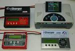
 Four DPS-600PB Power Supplies In Series Powering iCharger 4010Duo
Hope that all makes sense, and I hope this instructional DPS 600PB build article helps you out if you wish to build your own modular RC power supply just like what Mike at 2ZO-RC offered us before.
It's not a hard conversion, but it does take time and skill. It reconfirms how reasonably priced ($60 USD) 2ZO-RC's modded power supplies were in the first place.
Again, I thank Mike for making them available to us power charging hungry RC'ers at such a reasonable price. We will miss his modular power supplies, but you can certainly build your own with a little know how and time investment.
Visitor DPS 600PB Build & Feedback
Hi John - Thank you for the great information on your site.
I just successfully completed converting/building two DPS 600PB power supplies following your excellent, clear directions. A couple of comments you may want to incorporate if you feel appropriate.
I experienced difficulty separating the case after removing all the screws because the thick paper shielding/insulation was adhered to the case with double sided tape so the case top (the part with the fan attached) couldn't slide to release the dogs from the slots on the case side.
Below are a couple photos of how I separated the tape bond under the case top using a plastic chisel.
 DPS 600PB Build - Separating Insulating Paper From Top Panel
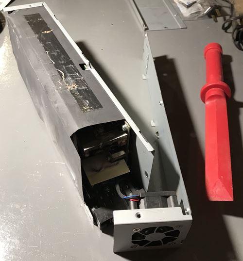
The second thing is that instead of messing with that white goo that secures the fan plug I simply unscrewed the fan from the case top and taped it out of the way.
 DPS 600PB Build Alternate Grounding Tab
I've got the two DPS 600PB power supplies held together with 2" Velcro. Seems to hold them well. You can also see I redesigned the ground tab, fastening it to the terminal mounting plate with a 10/32 screw. Looks a bit neater to my eye and doesn't add thickness under one corner of the case. Btw, not shown is my solution to breaking that ground connection. I drilled out the whole mounting stud and tacked a small piece of 1/4" rubber under the corner of the pc board with rtv silicone.
So I'm new at flying electrics and your information on the care and feeding of Lipos is invaluable. Thanks again and best holiday wishes to you and your family.
Jim - Maryland USA


Need Heli Help?
- Getting into the hobby but have no one to help you?
- Are you feeling overwhelmed & confused?
- Are you tired of wasting time seeking partial and conflicting information?
- Don't understand the maze of RC heli setup fundamentals?
- Is that sickening feeling after crashing turning you off the hobby?
- Are you simply ready to give up?
My RC Helicopter eBooks will help you with those exact problems. Grab your copies today.

Click Here For More Information

Click Here For More Information

Click Here For More Information
Recent Articles
-
The Ultimate RC Helicopter Tools Guide: What You Need & Why
Apr 10, 26 12:56 PM
 A complete breakdown of RC helicopter tools. Let's cover swashplate levelers, pitch gauges, hex drivers and much more to help you achieve a pro-level build.
 -
Best RC Battery Charger Guide: How to Choose the Right One
Apr 07, 26 02:29 PM
 Confused by Amps and Watts? Learn how to choose the best RC battery charger with this guide covering features, power, ratings, safety and much more.
 -
RC Power Supply Guide: Don't Starve Your RC Charger
Mar 31, 26 06:33 PM
 From low cost converted server power supplies to commercial grade options, let's find the best RC power supply for your specific RC battery charger.