Model Turbine Engine Service
by John Salt - Updated August 2021

I've documented this model turbine engine service to a MW54H Wren turbine helicopter engine and figured the process could perhaps make for an interesting article to share on my website.
I feel it might give a few folks a better understanding of the inner workings of a model turbine engine and what a basic model turbine service involves for anyone thinking of tackling the service on an MW54 or similar two stage model turbine themselves.
Before going any further however, I want to really thank Mike & Leonie Murphy (owners of Wren Power Systems) for all the help they gave me on this project.
2019 Update - Wren Power Systems is now owned by Turbine Solutions. They have parts and provide service for all Wren turbines.
I was extremely impressed with the time & help Mike offered; giving me detailed instructions of the tear down process, exactly what wear & tear items to look for & how to assess their condition, several parts options based on my budget, and many other useful model turbine overhaul & service tips.
The Wren MW54H engine is after all no longer in production being replaced by the MW44H & MW45i, so I kinda figured I might be on my own (SOL in other words)... How wrong I was. This truly was one of the most enjoyable projects I have undertaken in all my years of RC modelling.
The Model Turbine Engine Service Begins
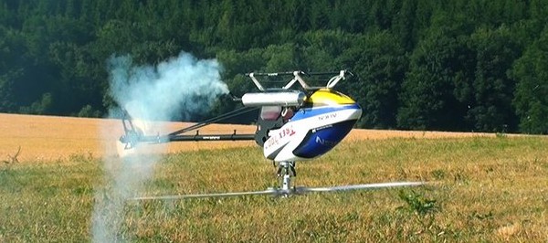
 Wren Turbine Engine Removed From Helicopter For Servicing/Overhaul
I guess the best place to start with any project is at the beginning.
I first realized my MW54H was due for a service based on the hours it had accumulated over the past 7 years of flying. Last summer I took an hour reading from the FADEC and was floored - just over 110hrs! The bearing service interval is about 70 hours on these engines so I was really shocked I had gone so far over, totally neglecting monitoring my time usage. Don't make that same mistake...
The engine was still running fine, but I had convinced myself I was detecting a little front bearing noise and no question, I was way over on hours so this winter was the perfect time to service/overhaul it.
I also really wanted to take this project on myself; both from a learning standpoint, and that of hopefully saving a few bucks. By doing it myself, I would only have to send the shaft/turbine assembly back to Wren in the UK so they could press a new bearing on, inspect the turbine, and dynamically re-balance the shaft and turbine assembly after the bearing install.
And lets face it, I really wanted to dive into the inner workings of this little beastie to better understand miniature turbine engine operation & design. I was one of those kids who always took their toys apart to see how they worked (sometimes they never worked again afterward) and I've never outgrown that curiosity to this day. Thankfully my track record of reassembling and repairing has improved by several orders of magnitude over the years. Sure hope that is the case with this little turbine...
 Wren Turbine Engine Split From Second Stage
The first job at hand was to split the engine from the second stage. Several of the interstage collar bolts were seized due to the high temperatures they are exposed to. As per Mike's advice, I just put some jet fuel on them and let them sit for an hour before making a second removal attempt. They came out easy breezy :-)
Learned something new, jet fuel makes a decent penetrating fluid to aid in the removal of seized fasteners.
Model Turbine Engine Compressor Damage
Starting into the tear-down was the first BIG surprise after I removed the starter motor & FOD screen housing. The leading edge of all the compressor blades were all chewed up and damaged! I was horrified I had been flying with this damage and didn't even realize it. For how long, I don't know?
 Compressor Damage Discovered
I still have no idea what caused this? The FOD screen had no holes in it and I never remember taking off or landing in an overly dirty area with any sort of small debris that could make it past the FOD screen.
The funny thing is the damage was completely confined to the front leading edge blades only, not the rear ones. There was also no damage to the turbine blades at the back of the engine or any chucks of debris found anywhere in the engine or second stage. That was a huge relief as I was thinking the entire engine could be junk if similar damage was discovered as I got deeper into disassembly.
 Close Up Of Wren Compressor Damage
After much thought, the only thing I can think of that may have caused this is ingesting ice into the engine. I do fly this heli in the winter sometimes and perhaps with the right set of conditions (high humidity), ice could form on the inside of the FOD screen or edge of the bell mouth duct and break off?
I really don't know if that's the cause, but it might explain why the damage was limited to the leading edge of the compressor and never made it deeper into the engine as the ice broke up and melted.
Just my hypothesis and I'll likely never know the actual cause, how long I had been flying it damaged like that, or in fact if it was a one time occurrence or the result of multiple occurrences? I will however limit my winter flying now and pay much closer attention to compressor inspections using a flashlight to peek inside on a regular basis now - basically after every flying session.
So, that was the first surprise I was faced with and the first replacement part to put on the list. These chewed up blades could also be the explanation of what I thought to be a noisier engine? It's not a far stretch to assume those rough leading edges would produce a fair amount of noise when spinning upwards of 120,000 RPM.
Removing the compressor from the shaft was fairly straight forward. The nut that holds it on is left hand thread and the compressor had to be heated up slightly with a heat gun in order to slide it off the front of the shaft; but other than those two little tips, it came off fairly easy.
With the compressor removed from the front of the shaft, the shaft and turbine easily slide out the back of the engine.
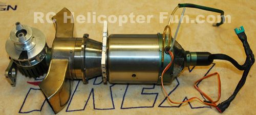
 Wren Turbine & Shaft After Removal
Shown above is the turbine and shaft assembly after removal. You can see the turbine (rear) bearing sandwiched between the turbine and shaft tube.
The way the lubrication system for both the front and rear bearings works is very simple. The front bearing is fed a small diverted portion of the jet fuel/oil mix under slight pressure by way of the front lubrication pipe. The lubrication first passes through the front bearing and travels down the shaft tunnel and then through the rear bearing where it is flung out onto the front side of the turbine and burnt off in the exhaust flow.
As you can appreciate, the faster the engine is running, the more lubrication these bearings receive as the fuel pump is pumping more fuel under higher pressures than it's at idle. This is the primary reason most model jet engine manufacturers suggest avoiding extended idling as it's the time where the least amount of lubrication is getting to the bearings.
Ceramic Bearing Inspection
 Accessing The Front Ceramic Bearing
With the intake, compressor, and seal plate removed, the front bearing is now visible.
I was impressed to see how well it was lubricated (nice and juicy), so the fuel-fed lubrication system by way of the front lubrication pipe has obviously been working well all these years.
I suppose that goes without saying since these bearings have over 110 hours on them. I at first could not detect in the slightest if this front bearing was worn at all.
The races felt tight and it was glass (or should I say ceramic) smooth. However, once I compared it to the new replacement bearings, I could detect the slightest amount of race play in the front bearing.
The rear one on the turbine end felt like new still, but with everything apart and having over a hundred hours on it, it of course was getting replaced.
The front bearing is easily pressed out from the back side of the engine. It can be replaced by the owner; just the rear one needs to be sent back to Wren for press fitting and dynamic balancing. This is MW54 specific as some models require both turbine and compressor dynamic balancing after a bearing replacement - check with your manufacturer.
These bearings by the way are classified as angular contact stainless ceramic hybrid, grade 5 Si3N4 ceramic balls. This means the races are made from stainless steel and the balls are Si3N4 ceramic (thus hybrid). Angular contact means the inside races are ever so slightly conical in shape which allows both radial and axial loading.
 Angular Contact Bearing Orientation Indicator
These little angular contact bearings are directional so you must install them facing the correct way so the axial loads are carried in the correct direction.
They have little arrows on the outer race to aid in correct orientation.
I purchased the two bearing set from Boca Bearing (Part Number JT-D688/602C). I only had to replace the two engine bearings as the second stage bearings still had good life left in them (they don't spin nearly as fast as the engine bearings do). I sent one new bearing along with the turbine and shaft to Wren for fitment, and kept the other one here for reassembly.
Combustion Chamber Inspection
Last item left in the engine tear down and inspection portion of the service is checking the combustion chamber and fuel distribution ring/needles. This presented the only real disassembly difficulty I ran into and also revealed another surprise I was not expecting.
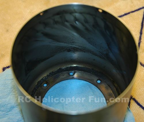 Interesting Carbon "Swirl" Pattern On Engine Case
This isn't the surprise, but I thought it was a neat photo to include because of the interesting carbon swirls on the inside of the engine case created by the redirected air flow from the compressor past the stator vanes into the combustor.
 Wren Turbine NGV Casting Was Very Difficult To Remove
The NGV (nozzle guide vane) casting was stuck onto the combustion chamber fairly well. Mike suggested I use a small nylon hammer to gently tap the edge of the casting (green arrows) to free it from the combustor. It took a while as I was being overly cautious, but it eventually came loose... The NGV must be removed in order to see inside the combustion chamber for inspection.
 Surprise, Surprise... Holes In Half Of The Vapourizer Tubes
It's hard to see, but in six of the twelve vapourizer tubes, there were little holes about 2/3rds of the way down each tube (white arrow pointing to one of them). Almost looks like the holes exploded outward, but I'm guessing they look like that because those little holes were very likely getting cherry hot and over time, deformed outward that way?
No doubt, these holes were causing poor combustion, hot & cold spots, and why I was noticing the engine flaming more during the start sequence just as the fuel pump was ramping up. A really good thing to find, but certainly not expecting it. The other issue was getting a replacement part. The only combustors Wren had for the MW54's were for the kero-start conversions and my engine is the gas-start type.
I didn't want to go to the fairly large expense of doing a kero-start conversion nor the expense of having Wren make a custom gas-start combustor (which Mike said they could do); so Mike once again came through with flying colors. He found a slightly used MW54 gas-start combustion chamber out of kero-start conversion they did a while back with very low hours on it. So he sold it to me for a great price and saved me a good deal of coin!
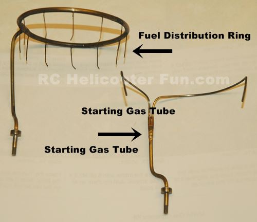 Fuel Distribution Pipes & Needles
Last item on the engine to inspect were the fuel tubes / needles for any damage.
The little stainless needles on the fuel distribution ring go down the center of each vapourizer tube in the combustor. They can't be rubbing on the side of the tubes and thus require careful alignment. As the fuel sprays out of the end of each needle into each tube, it's vapourized into a gaseous state for combustion. The stainless needles are thin and easily bent/damaged. The outlets in the ends are very small and even a tiny piece of dirt or lint could easily plug any of them.
This is the one area of the model turbine engine service that I was fanatically clean about. I first sprayed pressurized carb cleaner into the fuel ring pipe to clean out any dirt or carbon deposits. I carefully checked that each needle was squirting out cleaner ensuring no blockages and even flow between all of them. I then used filtered compressed air to blow the ring and needles dry. I plugged the end of the pipe to ensure nothing could get inside during reassembly.
The starting gas tube just diverts to two pipes and they go down opposite side vapor tubes in the combustor (for starting only). I cleaned them the same way as the fuel ring and needles but they are larger in diameter and not as easily blocked, cleanliness is still important regardless.
This pretty much wraps up the the engine side of the tear down and inspection. Parts needed include:
- Ceramic Hybrid Bearing Set (2 bearings): $160 USD
- New Compressor: $125 USD
- New Used Combustion Chamber: $65 USD
- New McCoy #9 Glow Plug: $10 USD
- Labor for Wren's turbine & shaft assembly inspection & bearing install and dynamic balancing plus shipping both ways: $275 USD
 MW54H Wren Turbine Engine Appart & Inspected
Wren Turbine Second Stage Inspection
 Wren Turbine Second Stage Appart For Inspection
I'm not going to get into much detail over the second stage because it was in very good shape.
I had to soak the interstage collar bolts with some jet fuel to help free them up same as I had to do on the engine end. The gears looked brand new which I was totally expecting knowing my dedicated yearly gear oil change and checking regiment. The two output gearbox bearings likewise seemed okay, but they are just normal bearings (not ceramic) so I replaced them anyway as they are inexpensive and I had everything apart.
Mike had me preform a spin test for the second stage shaft bearings & seal. The 2nd stage turbine shaft has one regular D688 bearing and a special stainless/phenolic bearing. Basically a spin test confirming silky smooth rotation and a specific number of rotations - the test passed without issue. The second stage turbine spins at less than half the speed of the engine turbine so these bearings should last longer.
I was obviously happy I didn't have to dig any deeper into the second stage at this point.
 Second Stage Wren Turbine Inspected & Looking Good!
Putting It All Back Together
Assembly is basically in the reverse order of disassembly. I was very glad I took a good number of photos during the disassembly to aid in correct position & orientation afterward. The time between the tear down and reassembly was also close to six weeks waiting for parts and such; and seeing that I can barely remember what I had for dinner last night, it goes without saying I forgot a good many aspects of parts orientation.
No real issues during reassembly. Cleanliness is of course paramount, and I made sure to oil the bearings with some turbine oil so they would not be running dry for several seconds during the first start-up. Any quality oil would likely do...
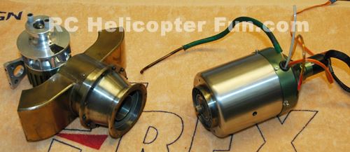
 New Garrett Compressor Ready To Go!
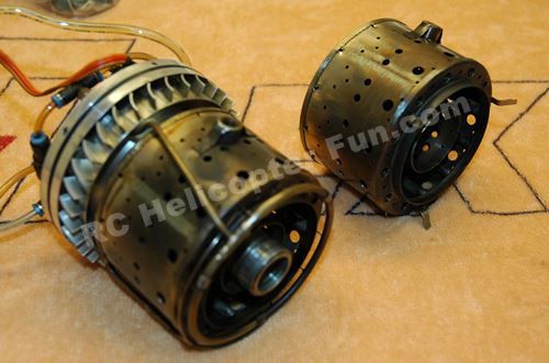 New "Used" Combustion Chamber On The Right
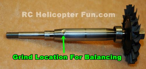 Turbine/Shaft Back From Wren With New Bearing & Balanced
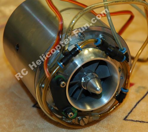 Almost Finished Putting Engine Back Together - No More Chewed Up Compressor :-)
Now the moment of truth!
Well, that's a relief!
It was so good to smell jet exhaust again after a 4 month hiatus; but more importantly, it actually started, ran, and didn't blow up in my face.
Since I took that video back in Spring 2016, I've put about 20 hours on the engine with no issues to report. No question it sounds and runs better than it did (just like new again), so the service was definitely needed and overdue.
Like I previously mentioned, this model turbine engine service / overhaul was a very enjoyable & rewarding process. I learned not only a great deal about what's involved in a model turbine engine service, but I also learned what I should be keeping a closer eye on moving forward.
 Good For Many More Years Of Flying Fun Hopefully...
As an Amazon Associate I earn from qualifying purchases.

Need Heli Help?
- Are you getting into the hobby and have no one to help you out?
- Are you feeling overwhelmed & confused?
- Are you tired of wasting time seeking partial and conflicting information?
- Is crashing due to not fully understanding helicopter setup turning you off the hobby?
- Are you simply ready to give up?
My RC Helicopter eBooks are here to help you with those exact problems.

Click Here For More Information

Click Here For More Information

Click Here For More Information
 Interested In RC Airplanes Too? Save Money With The Beginner's Combo Package
Recent Articles
-
OMPHobby RC Helicopters Let You Master The Skies
Apr 18, 24 07:21 PM
 Don't settle for anything less! OMPHobby RC Helicopters are built to last while taking your flying passion to a whole new level.
 -
Best Flybarless System In 2024 - Is There Such a Thing?
Apr 02, 24 09:08 PM
 Looking for the best flybarless system? Let's look at what's out there, pros & cons, features and pricing, to help you narrow your list.
 -
Learn How To Fly 3D Helicopter Aerobatics
Mar 15, 24 03:30 PM
 Want to learn how to fly 3D helicopter aerobatic maneuvers? Follow this skill building lesson plan to succeed.