Understanding the Differences Between Two Stage Turbines & Direct Drive Turbines
by John Salt - Updated August 2021
Two stage turbines and direct drive turbines – the two ways model jet engines produce horsepower and torque to spin RC helicopter rotor blades.
 Two Stage Turbine Engine with both Airplane & Helicopter Gear Boxes Shown
After learning all about how model jet engines work , we now know they spin very fast, compress large volumes of air, and then push all that pressurized air out the exhaust.
If that large volume of high pressure air exiting the engine is then also restricted through a jet nozzle, a good deal of thrust is produced.
This is fine for an RC jet powered airplane that relies on thrust to propel it through the air, but an RC helicopter needs to spin a rotor - we need rotational horse power called torque.
Direct Drive Turbines
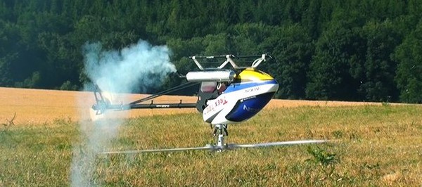
The first method of converting turbine power into rotational power for an RC turbine helicopter is to extend the turbine/compressor shaft out the rear or front of the engine and attach it to a gear reduction box or series of reduction gears & belts (as shown below).
 Typical Single Stage Direct Drive Model Turbine Helicopter Arrangement
The gear reduction then reduces the turbine shaft speed of
around 100,000 - 150,000 RPM by at least an order of magnitude (factor of ten or a more) to obtain a usable speed most main gear pinions spin at (in the range of 10,000 - 15,000 RPM).
This is the least expensive way to convert turbine power to
rotational horsepower and is the most common method due to the lower costs, but there are some problems with it.
First, all that pressurized exhaust air gets wasted since it is simply just blown out the exhaust nozzle/s.
This leads to the biggest problem of direct drive turbines, they are not as efficient. That lack of efficiency can however (design dependent) be made up by a single stage turbine in weight reduction over two stage designs as we will soon see.
The other fairly major issue with single stage is the turbine is directly connected to the gearing on the helicopter. This can be a problem as the turbine engine can get "loaded" down when the rotors do. Putting a large load on a turbine engine is far from ideal!
In addition to those two primary drawbacks, reducing the high RPM's of the engine down to more usable numbers for spinning a rotor blade requires significant gear reduction. Not a deal breaker by any means, but something to consider.
Two Stage Turbines
 Second Stage On The Left, First Stage On The Right
A two stage turbine is exactly what is used on most full size
helicopters and turboprop airplanes, commonly called a Turboshaft engine. Instead of wasting all that hot pressurized exhaust, it is used to turn another set of turbine blades mounted behind the turbine blades in the jet engine. This second turbine is correctly called a "Power or LP Turbine".
In essence, the jet engine's sole purpose when combined with a second stage power turbine is to act as a high volume air pump or more correctly called a "gas generator"; and is used to generate lots of air flow to spin the second stage turbines. These two turbines (the engine's and the second stage's) are not connected to each other with a shaft – they are completely independent of one another.
Think of it like two fans facing each other. If one fan is turned on, it causes the other fan to spin. For you car guys and gals out there, this is the same principle that is used in an automatic transmission torque converter.
The secondary turbine converts most of the hot pressurized exhaust back into
rotational horsepower and is hooked up to a reduction gear box to reduce the
speed down to a usable level – about 10,000 to 15,000 rpm for RC helicopters.

The above picture shows a two stage Wren MW44 model jet helicopter engine. Notice the collar (correctly called the INTERSTAGE) that is bolted onto the back of the jet engine. This is where the secondary "LP" turbine is located.
Bolted onto the back of interstage is the jet exhaust diverter. Behind the diverter, you can see the gear reduction box. This is a 90 degree gear box that allows for the more conventional "vertical" engine shaft placement that is used on most RC helicopters to drive the main gear.
The picture below shows the individual components of the second stage (power turbine section).
 2nd Stage "Guts"
 Looking Inside The Oil Filled Gear Box
 Looking At The Second Stage Turbine - Notice Grind Marks On The "Balance Ring" For Proper Dynamic Balancing
This
method of capturing the exhaust to spin another turbine increases
efficiently tremendously.
By using up most of this energy to spin another turbine, there is much less exhaust pressure force exiting the exhaust nozzle/s and the effects of jet exhaust pushing the heli around is largely eliminated. In fact, the air flow out the exhaust nozzles is less than what you would feel out of a hair dryer - albeit much hotter ;-)
The other big (huge in my opinion) benefit is you are not loading down the engine as you would with the direct drive method. There is no mechanical connection between the engine and the second stage/gear box. The second stage turbine only drives the load in other words and can tolerate a considerable mismatch between the engine and the second stage load.
This makes for a much smoother running model turbine engine, better engine management, better speed control, longer bearing life, reduced stress loads on the turbine, and reduced vibrations.
Of course a two stage turbine is more costly (both to purchase & when servicing) as there are two more expensive ceramic bearings on the second stage half (4 ceramic bearings in total for the entire assembly). That said, the second stage doesn't spin nearly as fast as the engine thereby eliminating large amounts of gear reduction.
Typical speeds would be engine @ 120,000 RPM and second stage around 50,000 RPM), so the second stage bearings last longer. I've got over 110 hours on mine and they still checked out to be in perfect condition when I serviced my engine's bearings.
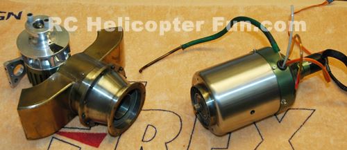
As I already mentioned, model two stage turbine engines weigh more than single stage ones. The second stage on my Wren MW-54H for example weighs a good deal more than the engine as seen below of each component on a scale.
 Turbine Engine = 498g
 Second Stage / Gear Box = 830g
Most of this "second stage weight" however is in the gear box, so when you take that into account compared to all the external gearing &/or belts required with a single stage arrangement, the overall weight difference is not really that much at all (if any).
These are all the two stage turbine benefits I considered before deciding on which method I wanted and could not be happier with my decision!
I had over 100 hours on my Wren two stage MW-54H turbine engine before I replaced the bearings and they were still in fairly good shape. Moreover, it only required bearings on the engine (gas generator) half, not the second stage (power turbine) half. Testament of a well designed power-plant considering bearing replacement is recommended at 70 hours.
Most single stage models state even less... 50 hour bearing life is a typical number.
Differences Between Model & Full Size Two Stage Turbines / Turboshaft Engines
Our model two stage turbines are a very simplified version of a full sized helicopter turboshaft engine. The basic principle of using the jet engine as a gas generator and the second stage as the power turbine are the same, as is using a right angled gear/reduction box, but those are where the similarities end.
Our RC model two stage turboshaft engines use a normal thrust producing model jet engine and simply bolt a power turbine and gear box to the back of it. This of course saves costs by utilizing an already existing and proven model jet engine as the power source. Full size truboshaft helicopter engines on the other hand are purpose designed for maximum power turbine efficiency and space management.
As we already learned on the how model jet engines work page, our little model engines are centrifugal-flow type and use a less efficient single centrifugal compressor over the much more efficient yet complicated axial-flow compressors.
Most (not all) full size helicopter turboshaft engines utilize a combined axial and centrifugal flow compressor design for maximum efficiency. Most also use a reverse flow type combustion chamber to save on space (not nearly as long).
If you are interested in the basic design and function of a full size helicopter two stage turboshaft engine, here is a great instructional video.

As an Amazon Associate I earn from qualifying purchases.

Need Heli Help?
- Are you getting into the hobby and have no one to help you out?
- Are you feeling overwhelmed & confused?
- Are you tired of wasting time seeking partial and conflicting information?
- Is crashing due to not fully understanding helicopter setup turning you off the hobby?
- Are you simply ready to give up?
My RC Helicopter eBooks are here to help you with those exact problems.

Click Here For More Information

Click Here For More Information

Click Here For More Information
 Interested In RC Airplanes Too? Save Money With The Beginner's Combo Package
Recent Articles
-
OMPHobby RC Helicopters Let You Master The Skies
Apr 18, 24 07:21 PM
 Don't settle for anything less! OMPHobby RC Helicopters are built to last while taking your flying passion to a whole new level.
 -
Best Flybarless System In 2024 - Is There Such a Thing?
Apr 02, 24 09:08 PM
 Looking for the best flybarless system? Let's look at what's out there, pros & cons, features and pricing, to help you narrow your list.
 -
Learn How To Fly 3D Helicopter Aerobatics
Mar 15, 24 03:30 PM
 Want to learn how to fly 3D helicopter aerobatic maneuvers? Follow this skill building lesson plan to succeed.