PID Basics
by David E. Buxton
 The 123 & "PID" of Flybarless Operation
This PID Basics article speaks from an RC helicopter pilot’s perspective while providing information and insights that are applicable for airplane pilots, multi-copter pilots and anyone else who might be interested in electronic stabilization.
This article uses mechanical illustrations so that the PID formulas become much more intuitive, much easier to visualize.
Our model helicopters used to use a mechanically stabilizing fly-bar system along with a tail gyro which offered a choice of rate mode or heading hold.
Turn up the gain until the tail wagged and then turn it down a bit. That was pretty much all that we could do. PID was something most of us had never heard about.
The more recently available flybarless gyro systems eliminate the mechanical fly-bar system. We also have a lot more control parameters to play with and it helps considerably if we understand what each adjustment is intended to do. Many are PID adjustments, even if the manufacturer does not use industry standard PID terminology.
Long before computers, long before electronics there were PID systems which were implemented using mechanical components. PID stabilization shows up in hundreds of industrial applications. Perhaps the first of these was developed to accurately auto-pilot ships across the ocean. By returning to the mechanical roots of PID, we can better understand how it works.
PID Basics For RC Helicopters
The following diagram illustrates where the PID calculations are located in the stability loop for tail control.

The receiver electronics identify where the tail should be. This is compared with where the gyro sensors calculate the actual position to be.
The difference is the error input to the PID formulas. The PID output determines how far to rotate the servo arm and the pitch of the tail rotor changes accordingly.
Even if you have studied calculus and understand what Proportional, Derivative and Integral (PID) mean does not make it easy to understand how PID affects the flight of your flying machine. The objective of this article is to use mechanical examples that will make it much easier to visualize how a PID system works.
Imagine strapping your helicopter’s skids to a Lazy Susan turn table so that it can spin freely. With all the PID gains set to zero, we spool up the head speed and the heli spins vigorously in the opposite direction. The pirouette can be brought to a stop using mechanically illustrated PID components.
Proportional (P)

Start by attaching a spring to the tail of the helicopter. Spring tension and length will perform as a proportional element.
The harder we pull a spring, the longer it gets and it pulls back with equally increasing intensity. P alone is inherently prone to oscillation.
A text book ideal load hanging from an ideal spring (in a vacuum with no spring losses) will continue to bounce forever.
Derivative (D)

Derivative (D) acts as a shock absorber which resists change (ignore the spring that is part of a typical shock absorber).
A mechanical shock absorber uses a piston with a leak hole, in a fluid filled cylinder. Slowly pull the piston and it offers very little resistance.
Give it a jerk and it vigorously fights back. The resistance to change is proportional to how fast you try to move it.
In our mechanical example, increasing D-Gain is accomplished by thickening the fluid or reducing the size of the hole in the piston. The shock absorber gets much stiffer. The derivative of a signal is proportional to its rate of change. The mechanical representation of a shock absorber seems quite innocent.
An electronic derivative is very sensitive to noise. Properly shock mounting your gyro module is important so that the D component of your PID does not get overloaded or swamped into spastic paralysis. More expensive flybarless systems do a better job of low pass filtering vibration noise. Higher speed digital gyro computing also helps.
Combining P and D

Mechanically, P and D use a spring with a shock absorber. A rate mode gyro uses PD stabilization.
Increasing D-Gain reduces P oscillation. Stability is increased at the expense of agility. A truck suspension uses a lot more P and D for a much stiffer ride.
Some stabilization systems do not provide a D-Gain adjustment. The electronic stabilization does not need any D because there is sufficient dampening from the load. There may be some D-Gain set as an unavailable constant. Load stability is often resistive, like a sanding block on wood rather than derivative behavior like a shock absorber. Air resistance dampening is velocity squared.
Integral (I)

A motor driven worm drive is illustrative of the Integral (I) process, which is a dynamically adjusted trim over time that zeros the error.
Motor speed is proportional to the error. The change in offset slows to zero when the error is reduced to zero. I-Gain introduces accuracy to a control system, which P and D cannot accomplish (e.g. ships crossing the ocean under auto pilot control can maintain heading accuracy to a fraction of a degree).
Governors (e.g. for helicopters) make use of the Integral process to maintain head speed as the battery is discharged during flight. The Integral slowly increases the throttle setting so that the average head speed does not decline.
Below is a great video that demonstrates how each control loop of PID affects the stabilization on a single axis lifting propeller.
PID Waveforms
With that video in mind and seeing (not too well) the changing waveforms on the monitor, let's have a closer look at these PID waveforms.
The following waveforms are based on a very simple simulation using PID formulas and a “perfect” load; very similar to the example in the video. The blue trace line on the graphs represents the desired or target value (ie. the target height of the propeller/motor apparatus using the example from the video). The Red line represents the actual registered position (ie. the real time position of the propeller/motor apparatus).
1. Dial up the P-Gain, with no damping, and the oscillation continues forever just as it did in the video.
2. Dial up D-Gain and the oscillation is dampened out, but there is still a steady state error (the propeller/motor apparatus never reaches its desired height).
3. Increase D-Gain further and the oscillations slow even quicker; however, the steady state error is still present.
4. Dial I-Gain slowly trims the waveform average so that the red waveform closes in on the blue step target waveform and the propeller/motor apparatus locks in on the desired height.
5. Too much I-Gain can make a P-Gain problem look worse.

PID Basics - Integral Oscillation
The integral process is constantly trying to reduce the error to zero. Think worm drive, with the illustrated motor slowly dithering back and forth in response to small amounts of error. For your model helicopter, factor in small amounts of linkage slop, servo resolution, control rod flexing and plenty of opportunities for tiny amounts of binding along the control path.
The integral process is constantly trying to resolve that mess. Some heli pilots get obsessive (for good reason) about getting the tail control mechanics as ultra silky smooth as possible, so they can turn the I-Gain up a little bit more.
PID Basics - Making Adjustments
The following table is adapted from Wikipedia’s PID Control web page. It predicts what will happen with regards to rise time, overshoot, error, etc. when each of the three PID gain settings are increased.

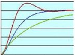
Refer to the three waveforms at the left.
A faster rise time would accelerate the start and stop of a roll or pirouette. P-Gain and D-Gain are a tradeoff, e.g. to solve an overshoot or oscillation problem.
Error behavior is illustrated by seeing the tail move when you punch in full collective. The integral process brings the tail back to where it was in the hover.
Another Good PID Basics Video
You will probably agree that the mechanical illustrations for P, I and D have provided you with a much more intuitive feel for how PID systems work. The chances have been improved that when you notice a heli performance improvement opportunity, that you will know which adjustment to try first.
We can better appreciate that the FBL modules allow us to get at the PID and other parameters that used to be hidden from us. Time to go and have some more RC helicopter fun.
David is an electrical engineer at Tektronix. There he works with oscilloscopes, spectrum analyzers, logic analyzers, video monitors and generators.
Question/s for Dave? Feel free to use the contact form below...

As an Amazon Associate I earn from qualifying purchases.

Need Heli Help?
- Are you getting into the hobby and have no one to help you out?
- Are you feeling overwhelmed & confused?
- Are you tired of wasting time seeking partial and conflicting information?
- Is crashing due to not fully understanding helicopter setup turning you off the hobby?
- Are you simply ready to give up?
My RC Helicopter eBooks are here to help you with those exact problems.

Click Here For More Information

Click Here For More Information

Click Here For More Information
 Interested In RC Airplanes Too? Save Money With The Beginner's Combo Package
Recent Articles
-
Best Flybarless System In 2024 - Is There Such a Thing?
Apr 02, 24 09:08 PM
 Looking for the best flybarless system? Let's look at what's out there, pros & cons, features and pricing, to help you narrow your list.
 -
Learn How To Fly 3D Helicopter Aerobatics
Mar 15, 24 03:30 PM
 Want to learn how to fly 3D helicopter aerobatic maneuvers? Follow this skill building lesson plan to succeed.
 -
How To Check & Replace Ball Links Video
Feb 25, 24 12:32 PM
Quick video showing how to check RC Ball Links to determine if they need replacement. We will then replace these worn out RC helicopter links, making sure to get correct adjustment off the bench. Quic…