Appreciating Digital Servos
Current Probe Experiment
by David E. Buxton July 25, 2014
Understanding how digital servos work, as a switched mode power device, will help you to make better use of them and gain a better understanding of their power supply requirements. We will take a look at digital servos through the “Eyes” of a current probe and oscilloscope.
Switched Mode Power

Digital like analog servos use pulse width and pulse rate modulation in order to rotate the servo motor. The servo can be pulsed in the forward or reverse direction. The four solid state switches, under the control of the servo’s micro controller, are either open circuit or closed circuit for Ohms law efficiency.
Through the "Eyes" of a Current Probe

The experiment used a Airtronics 94780 coreless digital servo, 5 VDC power supply, Tektronix TCP0030 current probe and Tektronix DPO7354 digitizing oscilloscope. The waveforms that follow were downloaded from the oscilloscope.
For the following waveform I applied an aggressive amount of torque with my fingers. The servo was making enough noise to convince me that it was under duress and it was aggressively holding position. Average current was 0.3 Amps which is what a Digital Multi Meter (DMM) would read. Peak current was 5 Amps. We can calculate that the servo’s resistance at zero RPM is 1 Ohm while a pulse is active (5 volt supply divided by 5 Amp current = 1 Ohm).

The pulses were much more sparsely scattered under moderate loads, sometimes a single pulse, sometimes a small cluster of pulses.
For the next waveform I was considerably more assertive in the amount of torque that I applied, more than what you would expect during aggressive flight conditions. As you can see, the pulse rate has doubled without increasing pulse width. Peak current was 5 Amps and average current 0.5 Amps.

DC Servo Motor Basics

Moving From Position A to Position B
The waveform below shows what it takes to get the motor moving. The current pulses get shorter as the motor speeds up and generates a proportionally increasing voltage so that pulse height declines to almost zero amplitude and the motor can spin no faster. The pulses are not getting shorter because the power supply is bogging down, but because of the motor is simultaneously a motor and a generator.

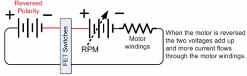
Referring to the second cluster of pulses in the graph below, pulse height almost doubles when the micro controller works to bring the motor to a stop. The FET switches have reversed the pulse polarity so that the power supply and the servo motor’s “battery” are adding up in series.

The motor’s internally generated voltage is proportional to RPM and so the voltage graph will have the same shape as the RPM graph above. Increase the voltage reaching the motor and the servo can achieve a higher maximum speed.
The following is what happens when you repeatedly run the servo back and forth, e.g. when "stirring the sticks":

Peak current is 9.3 Amps and average current consumption is 1.3 Amps for the data record displayed above. Four servos would consume an average of 5.3 Amps. The pulse peak would be 37 Amps when all four servos happened to reverse exactly in sync.
Adding Capacitance
Repeatedly moving the servo back and forth is the worst case scenario and draws considerably more current than having the servo hold position against an aggressive load.
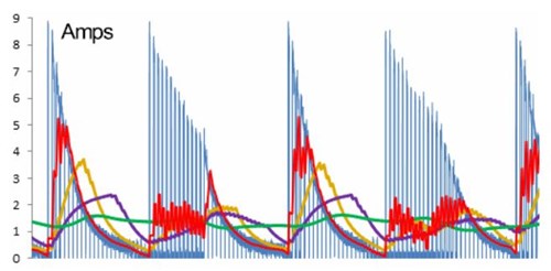
The digitized data for the blue graph above records a peak current of 9.3 Amps and average current is calculated to be 1.3 Amps, which is what a DMM would read. The only way we can reduce the peak current is with a capacitor. The larger the capacitor the closer we can get to the calculated 1.3 Amp average current (the DMM reading).
The red, orange, purple and green waveforms above simulate what happens respectively using four increasingly larger amounts of capacitance. Some BEC manufacturers use a large valued capacitor and a lower Amps rating. Castle Creations uses very little capacitance and higher Amps rated BECs. These design tradeoffs will be better understood after reading the Receiver Power Supply article.
Digital Servo Summary
Digital servos use switched mode power which is considerably more efficient than the analog power alternative. Pulses can be very tall and very thin, with the tallest current pulses occurring when the motor is at full speed and then reversed. Stirring the sticks puts a much more aggressive load on the power supply than pulling out of a power dive. Capacitance can be used to average the current so that the power supply can meet peak demand.
The Receiver Power Supply article is the recommended follow up.
David is an electrical engineer at Tektronix. There he works with oscilloscopes, spectrum analyzers, logic analyzers, video monitors and generators.
Question/s for Dave? Feel free to use the contact form below...

As an Amazon Associate I earn from qualifying purchases.

Need Heli Help?
- Are you getting into the hobby and have no one to help you out?
- Are you feeling overwhelmed & confused?
- Are you tired of wasting time seeking partial and conflicting information?
- Is crashing due to not fully understanding helicopter setup turning you off the hobby?
- Are you simply ready to give up?
My RC Helicopter eBooks are here to help you with those exact problems.

Click Here For More Information

Click Here For More Information

Click Here For More Information
 Interested In RC Airplanes Too? Save Money With The Beginner's Combo Package
Recent Articles
-
OMPHobby RC Helicopters Let You Master The Skies
Apr 18, 24 07:21 PM
 Don't settle for anything less! OMPHobby RC Helicopters are built to last while taking your flying passion to a whole new level.
 -
Best Flybarless System In 2024 - Is There Such a Thing?
Apr 02, 24 09:08 PM
 Looking for the best flybarless system? Let's look at what's out there, pros & cons, features and pricing, to help you narrow your list.
 -
Learn How To Fly 3D Helicopter Aerobatics
Mar 15, 24 03:30 PM
 Want to learn how to fly 3D helicopter aerobatic maneuvers? Follow this skill building lesson plan to succeed.